Waste discharge die cutting machine

A die-cutting machine and die-cutting knife technology, applied in metal processing and other directions, can solve the problems of danger, pressing on the arm, occupying working time, etc., to achieve the effect of effective waste cleaning, convenient waste collection, and improved production efficiency

Inactive Publication Date: 2015-10-28
TRIUMPHLEAD ELECTRONICS TECH CHENGDU CO LTD
View PDF6 Cites 15 Cited by
  • Summary
  • Abstract
  • Description
  • Claims
  • Application Information

AI Technical Summary

Problems solved by technology

[0003] The waste generated by the existing die-cutting machine during die-cutting often needs to be handled manually. Since the die-cutting knife of the die-cutting machine performs rapid up-and-down reciprocating motion during die-cutting, it is necessary to stop the machine when manually cleaning the waste, and the stoppage will take up work. time, but if the waste is cleaned without shutting down, it is easy to cause accidents such as pressing on the arm, which is very dangerous

Method used


Image

  • Waste discharge die cutting machine
  • Waste discharge die cutting machine
  • Waste discharge die cutting machine

Examples


Embodiment Construction

[0011] The following will clearly and completely describe the technical solutions in the embodiments of the present invention with reference to the accompanying drawings in the embodiments of the present invention. Obviously, the described embodiments are only some, not all, embodiments of the present invention. Based on the embodiments of the present invention, all other embodiments obtained by persons of ordinary skill in the art without making creative efforts belong to the protection scope of the present invention.

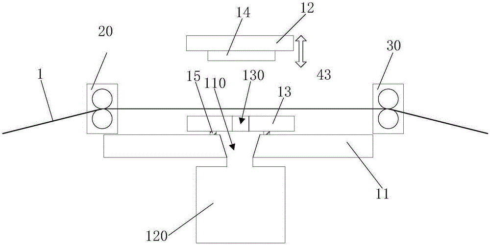
[0012] see figure 1 , is a schematic structural diagram of a waste discharge die-cutting machine according to an embodiment of the present invention. The waste discharge die-cutting machine in this embodiment includes a die-cutting mechanism, a feeding mechanism 20 and a pulling mechanism 30 .

[0013] The die-cutting mechanism includes a base 11 , an upper die holder 12 , a lower die holder 13 and a die-cutting knife assembly 14 . A waste material tank 110 ...


PUM


Abstract

The invention provides a waste discharge die cutting machine, which comprises a feeding mechanism, a material pulling mechanism and a die cutting mechanism, wherein the die cutting mechanism comprises a base, an upper die seat, a lower die seat and a die cutting tool assembly, a waste material groove is arranged in the base, a waste material collection box is arranged below the waste material groove, the lower die seat is connected onto the base, the lower die seat is provided with a material falling hole corresponding to the waste material groove, the upper die seat is arranged above the lower die seat, the upper die seat can move in a vertical reciprocating mode in the vertical direction in relative to the lower die seat, the die cutting tool assembly comprises a cutting tool body, buffer springs and a material squeezing column, the cutting tool body is connected onto the lower side surface of the upper die seat via the buffer springs, the cutting tool body is provided with a through hole matched with the material falling hole, a sealed ring-shaped blade surrounds the circumference of the through hole, the material squeezing column is arranged on the lower side surface of the upper die seat and located between the blade and the upper die seat, the material squeezing column is matched with the through hole, and the feeding mechanism and the material pulling mechanism are arranged at two sides of the lower die seat respectively. Waste material can be automatically collected in a non-power off condition.

Description

technical field [0001] The invention relates to the technical field of die-cutting, in particular to a waste discharge die-cutting machine. Background technique [0002] Die-cutting machine is divided into flat die-cutting machine, rotary die-cutting machine, optical calibration die-cutting machine, mainly used for some corresponding non-metallic materials, self-adhesive, EVA, double-sided tape, electronics, mobile phone rubber pad, etc. Cutting (full cut, half cut), indentation and bronzing operations, the die-cutting machine uses steel knives, metal molds, steel wires (or templates carved from steel plates), and applies a certain pressure through the embossing plate to print the printed matter or cardboard Rolling and cutting into a certain shape is an important equipment for post-press packaging processing. [0003] The waste generated by the existing die-cutting machine during die-cutting often needs to be handled manually. Since the die-cutting knife of the die-cutting...

Claims


Application Information

Patent Timeline
Patent Type & Authority Applications(China)
IPC IPC(8): B26F1/38B26D7/18
CPCB26F1/44B26D7/1818
Inventor 王利贺根洪
Owner TRIUMPHLEAD ELECTRONICS TECH CHENGDU CO LTD
Why Eureka
Try Eureka