Enlarged chamber alleviation structure on end part of high-speed railway tunnel

A technology for high-speed railways and tunnels, applied in tunnels, mining equipment, earthwork drilling and mining, etc., can solve the problems of high cost, poor economy, high construction cost, etc., and achieve the goal of reducing pressure gradient, reducing influence, and reducing the peak value of micro-pressure waves Effect

Inactive Publication Date: 2015-10-28
SOUTHWEST JIAOTONG UNIV
View PDF4 Cites 8 Cited by
  • Summary
  • Abstract
  • Description
  • Claims
  • Application Information

AI Technical Summary

Problems solved by technology

At present, the commonly used technical measures for the mitigation of micro-pressure waves in high-speed railway tunnels are as follows: 1. Set up shafts above the tunnels to reduce the peak pressure gradient of compression waves through shaft pressure relief. It is very large, the shaft construction is difficult and costly, and this decompression method is difficult to popularize and use; two, expand the cross-sectional area of ​​the tunnel, and decompress by reducing the blocking ratio (the ratio of the cross-sectional area of ​​the train to the cross-sectional area of ​​the tunnel). method, the amount of tunnel construction has increased greatly, and its construction cost is high, so its use is also limited; 3. To improve the airtightness of rolling stock, this method can only improve the riding environment in the compartment and improve the ride comfort of passengers , but when the airtightness of the locomotive reaches a certain level, in order to improve the airtightness, the technical difficulty is high, the maintenance cost is high, and the economy is poor, so it cannot be popularized and used; Due to the constraints of terrain conditions, this method is often not feasible
5. At present, the slab ballast bed is widely used, and the micro-pressure wave generated by the high-speed railway entering the tunnel tends to amplify with the increase of the tunnel length, and it is difficult to set up a micro-pressure wave mitigation device at the entrance of the tunnel to meet the requirements

Method used


Image

  • Enlarged chamber alleviation structure on end part of high-speed railway tunnel
  • Enlarged chamber alleviation structure on end part of high-speed railway tunnel
  • Enlarged chamber alleviation structure on end part of high-speed railway tunnel

Examples


Embodiment Construction

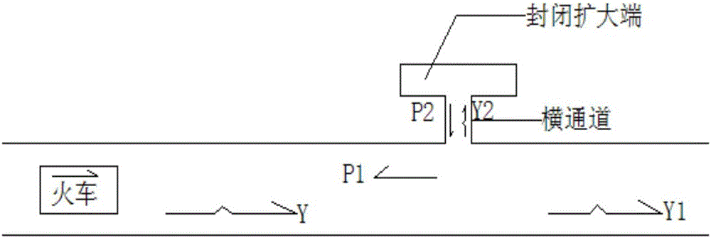
[0020] Such as Figure I As shown, when the high-speed train enters the tunnel, the air in front of the train is compressed, and a compression wave is generated. The compression wave is represented by Y in the figure, and the expansion wave is represented by P. It can be seen that when the compression wave Y generated in front of the train propagates to the chamber, it is divided into three parts, one of which is reflected in the form of expansion wave and propagates toward the tunnel entrance. Figure I P1 in ; the other two parts propagate along the forward and transverse channels of the tunnel respectively in the form of compression waves, as shown by Y1 and Y2 in the figure. When Y2 propagates along the transverse channel to the closed expansion end, part of it is transmitted to the closed expansion end in the form of waves of the same sign, and undergoes repeated complex reflection processes until it disappears; channel, and then generate two waves of the same sign that ...


PUM


Abstract

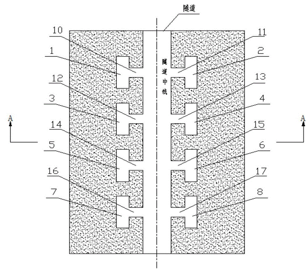
The invention discloses an enlarged chamber alleviation structure on the end part of a high-speed railway tunnel. The enlarged chamber alleviation structure is arranged in the vicinity of the end part of the high-speed railway tunnel, is used for reducing a pressure gradient and a micro-pressure wave peak of compression waves at a tunnel portal, and is characterized in that enlarged chambers are formed in the two transverse sides of the tunnel respectively, wherein the chambers are connected with the tunnel through linking taxiways; the sizes of the chambers are 80 to 130m<3>; the lengths of the linking taxiways are ranged from 2m to 20m, and can be selected according to engineering requirements, and the sectional areas of the linking taxiways are 20 to 40m<2>. According to the structure, the pressure gradient of the compression waves is obviously reduced, the micro-pressure wave peak generated when the compression waves reach the exit of the tunnel is greatly reduced, and the influence of running of a high-speed train on the surrounding of the tunnel is reduced.

Description

technical field [0001] The invention relates to a railway tunnel, in particular to a micro-pressure wave buffer structure arranged in a tunnel body for a high-speed railway. Background technique [0002] With the opening of the Beijing-Tianjin Intercity Express Line, Zhengxi, and Wuhan-Guangzhou Passenger Dedicated Lines with a speed of 350km / h, it marks that my country's high-speed train technology is becoming more and more perfect, so that Chinese people can look forward to the travel problems that will plague 1.3 billion people in the near future can be completely resolved. Of course, with the increase of the speed of high-speed railway, it will also cause many new problems. When a train enters a railway tunnel at high speed, an initial compression wave will be generated in front of the train, and this wave will propagate forward along the tunnel. When the compression wave reaches the exit of the tunnel, it will be reflected to the entrance as an expansion wave. At the s...

Claims


Application Information

Patent Timeline
Patent Type & Authority Applications(China)
IPC IPC(8): E21D9/14
Inventor 王英学高波申玉生任文强常乔磊刘健何俊叶畅
Owner SOUTHWEST JIAOTONG UNIV
Why Eureka
Try Eureka