Pressure sensing throttling valve

A technology for sensing throttle valves and pressure sensors, applied to multi-way valves, valve devices, engine components, etc., can solve problems such as cumbersome design

Inactive Publication Date: 2015-10-28
SUZHOU FURUN MACHINERY
View PDF8 Cites 2 Cited by
  • Summary
  • Abstract
  • Description
  • Claims
  • Application Information

AI Technical Summary

Problems solved by technology

[0002] The current throttle valve is realized with a relatively complicated structure, and the design is relatively cumbersome

Method used


Image

  • Pressure sensing throttling valve

Examples


Embodiment Construction

[0014] The present invention will be further described below in conjunction with the accompanying drawings and specific embodiments.

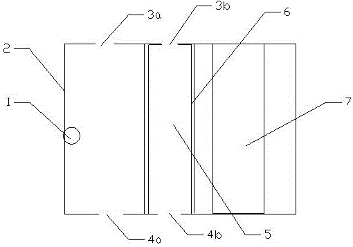
[0015] according to figure 1 , a pressure sensing throttle valve, comprising a valve body 2, characterized in that it also includes a first liquid inlet 4a and a second liquid inlet 4b at one end of the valve body, and a first liquid outlet 3a at the other end of the valve body And the second liquid outlet 3b also includes a plug-in throttling part 7 located on the valve body, and the throttling part is set through the valve body. The manner in which the plug-in throttling part penetrates the throttling valve is: parallel to the flow direction of the liquid. The direction of flow of the liquid is in figure 1 Middle is bottom-up. The plug-in throttle valve is detachable.

[0016] It also includes a pressure sensor 1 located on the inner surface of the valve body, and the pressure sensor is connected to a display device outside the throttle v...


PUM


Abstract

The invention belongs to the field of pipe fittings, and particularly relates to a pressure sensing throttling valve. The pressure sensing throttling valve comprises a valve body and is characterized by comprising a first liquid inlet, a second liquid inlet, a first liquid outlet and a second liquid outlet, and further comprising a push-pull-type throttling portion located on the valve body, wherein the first liquid inlet and the second liquid inlet are located at one end of the valve body, and the first liquid outlet and the second liquid outlet are located at the other end of the valve body; and the throttling portion penetrates the valve body. The pressure sensing throttling valve is simple in structure, capable of controlling the throttling degree and good in throttling effect and has the certain solid filtering function.

Description

technical field [0001] The invention belongs to the field of pipe fittings, in particular to a pressure sensing throttle valve. Background technique [0002] The current throttling valve is realized with a relatively complex structure, and the design is relatively cumbersome. Contents of the invention [0003] The object of the present invention is to overcome the above problems and provide a pressure sensing throttle valve with simple structure, controllable throttling degree, good throttling effect and certain solid filtering function. [0004] In order to achieve the above object, the technical solution adopted by the present invention is: a pressure sensing throttle valve, including a valve body, characterized in that it includes a first liquid inlet and a first liquid outlet at one end of the valve body, and a first liquid outlet at one end of the valve body. The first liquid outlet and the second liquid outlet at the other end of the body also include a plug-in ...

Claims


Application Information

Patent Timeline
IPC IPC(8): F16K11/00F16K37/00F16K51/00
CPCF16K11/00F16K37/005F16K51/00
Inventor 张国红
Owner SUZHOU FURUN MACHINERY
Why Eureka
Try Eureka