Interface circuit

A technology of interface circuit and conversion circuit, applied in the field of interface circuit, can solve the problem that it is difficult to reduce the manufacturing cost of control substrate, and achieve the effect of simple structure and reduced manufacturing cost.

Active Publication Date: 2010-10-06
BROTHER KOGYO KK
View PDF4 Cites 5 Cited by
  • Summary
  • Abstract
  • Description
  • Claims
  • Application Information

AI Technical Summary

Problems solved by technology

Therefore, it is difficult to reduce the manufacturing cost of the control board

Method used


Image

  • Interface circuit
  • Interface circuit
  • Interface circuit

Examples


Embodiment approach 1

[0043] Hereinafter, the present invention will be described in detail with reference to the drawings showing a preferred embodiment 1. FIG.

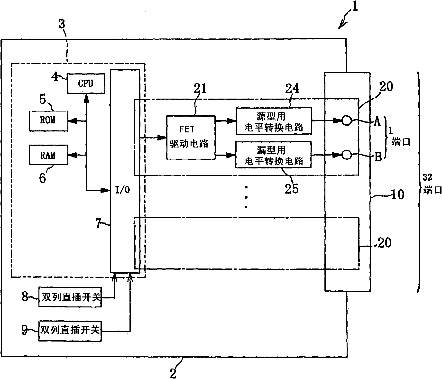
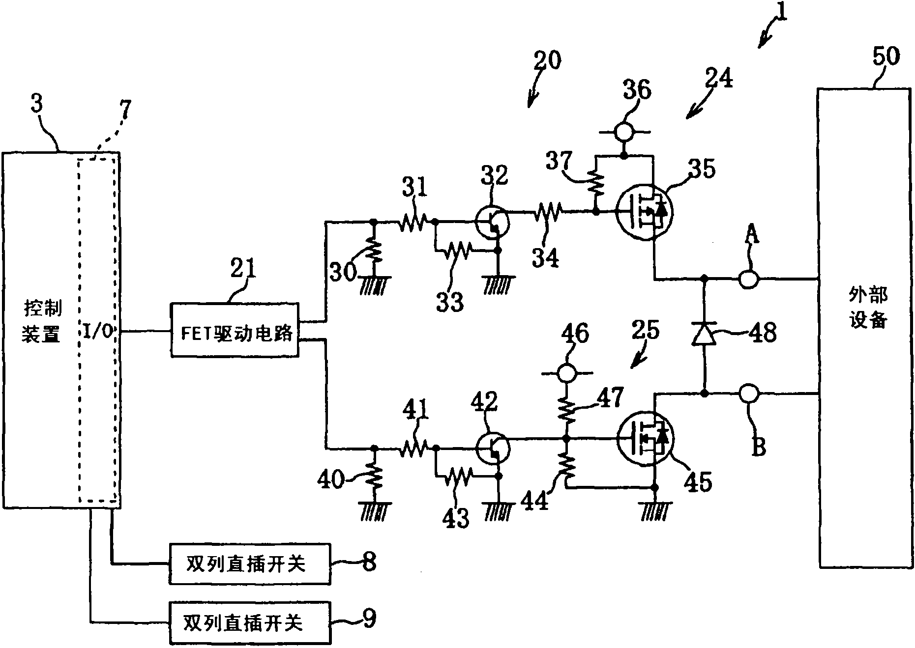
[0044] The output interface circuit 1 is set in the numerical control device of the machine tool. like figure 1 , figure 2 As shown, the output interface circuit 1 has a control device 3 , 32 output circuit units 20 , two dip switches (selection switches) 8 and 9 , and a terminal board 10 . The terminal board 10 includes 32 ports. Each port can be configured with two terminals. Terminal A and terminal B described later are disposed on this port.

[0045] The output interface circuit 1 is mounted on the substrate 2 . The control device 3 has a CPU 4 , a ROM 5 , a RAM 6 , and an input / output interface (I / O) 7 . The DIP switches 8 and 9 and the FET drive circuit 21 are connected to the input / output interface 7 . The control device 3 controls the drive of the FET drive circuit 21 described later in accordance with the selection made ...

Embodiment approach 2

[0084] Hereinafter, the present invention will be described in detail with reference to drawings showing a preferred embodiment 2. FIG.

[0085] according to Image 6 Next, the configuration of the input interface circuit 11 will be described.

[0086] The input interface circuit 11 is provided in the numerical control device of the machine tool. The input interface circuit 11 has a control device 13 , 32 input circuit units 200 , two dip switches (selection switches) 18 and 19 , and a terminal board 60 . The terminal board 60 includes 32 ports. Each port can be configured with two terminals. Terminals J and K described later are disposed on this port.

[0087] The input interface circuit 11 is installed on the substrate 12 . The control device 13 has a CPU 14 , a ROM 15 , a RAM 16 , and an input / output interface (I / O) 17 . The control device 13 controls the FET drive circuit 210 according to the selection made by the dip switches 18 and 19 . The input / output interface ...

Embodiment approach 3

[0129] Hereinafter, the present invention will be described in detail with reference to the drawings showing a preferred third embodiment.

[0130] according to Figure 11 The configuration of the input / output interface circuit 300 will now be described.

[0131] The input / output interface circuit 300 provided in the machine tool numerical control device includes an output interface circuit 1 and an input interface circuit 11 .

[0132] The output interface circuit 1 has a control device 3 , 32 output circuit units 20 , two dip switches 8 and 9 , and a terminal board 10 . The terminal board 10 includes 32 ports. Each port can be configured with two terminals. Terminal A and terminal B are arranged on this port.

[0133] The output interface circuit 1 is mounted on the substrate 2 . The control device 3 has a CPU 4 , a ROM 5 , a RAM 6 , and an input / output interface (I / O) 7 . The DIP switches 8 and 9 and the FET drive circuit 21 are connected to the input / output interface...


PUM


Abstract

An output interface circuit comprises a terminal connected with an external equipment, a source level converting circuit connected with the terminal, a drain level converting circuit connected with the terminal, a dip switch and a control device; when the operator operates the dip switch to select the source output corresponding mode, the source level converting circuit converts the level of an output signal of the control device to a high level and outputs to the external equipment; when the operator operates the dip switch to select the drain output corresponding mode, the drain level converting circuit converts the level of the output signal of the control device to a high level and outputs to the external equipment; an input interface circuit comprises a terminal connected with the external equipment, the dip switch, the drain level converting circuit connected with the terminal, the source level converting circuit connected with the terminal, and the control device; when the operator operates the dip switch to select the drain input corresponding mode, the drain level converting circuit converts the level of an input signal of the terminal to a low level and inputs to the control device; when the operator operates the dip switch to select the source input corresponding mode, the source level converting circuit converts the level of the input signal of the terminal to a low level and inputs to the control device.

Description

technical field [0001] The present invention relates to an interface circuit for outputting a source (PNP) signal or a sink (NPN) signal to an external device and an interface circuit for inputting a source or sink signal from an external device. Background technique [0002] A numerical control device for a machine tool includes an interface circuit for outputting signals to external equipment and an interface circuit for inputting signals to external equipment. When the input and output signals of the external equipment are source-type signals, the numerical control device uses a source-type interface circuit. When the input and output signals of external equipment are sink-type signals, the numerical control device uses a sink-type interface circuit. When the type of the interface circuit of the numerical control device does not match the type of the input and output signals of the external equipment, the operator needs to replace the interface circuit of the numerical c...

Claims


Application Information

Patent Timeline
Patent Type & Authority Applications(China)
IPC IPC(8): H02M1/06
Inventor 鹈饲敏明矶田康吉青木起男芳贺大辅
Owner BROTHER KOGYO KK
Why Eureka
Try Eureka