Bidirectional switch circuit and power converter having the same

A bidirectional switching circuit and power conversion device technology, which is applied in the direction of output power conversion devices, high-efficiency power electronic conversion, circuits, etc., can solve the problems of increasing the number of components, increasing the loss and damage of the conduction state, and achieving the reduction of components The effect of increasing the number of parts and preventing delay and loss

Active Publication Date: 2011-03-30
DAIKIN IND LTD
View PDF6 Cites 5 Cited by
  • Summary
  • Abstract
  • Description
  • Claims
  • Application Information

AI Technical Summary

Problems solved by technology

[0009] However, as mentioned above, if a bidirectional switch circuit is formed by installing reversely parallel diodes on each of the switching elements, this part will increase the number of components, complicate the circuit, and increase the on-state loss, which becomes a problem.
[0010] In this regard, as in the configurat

Method used


Image

  • Bidirectional switch circuit and power converter having the same
  • Bidirectional switch circuit and power converter having the same
  • Bidirectional switch circuit and power converter having the same

Examples


no. 1 approach

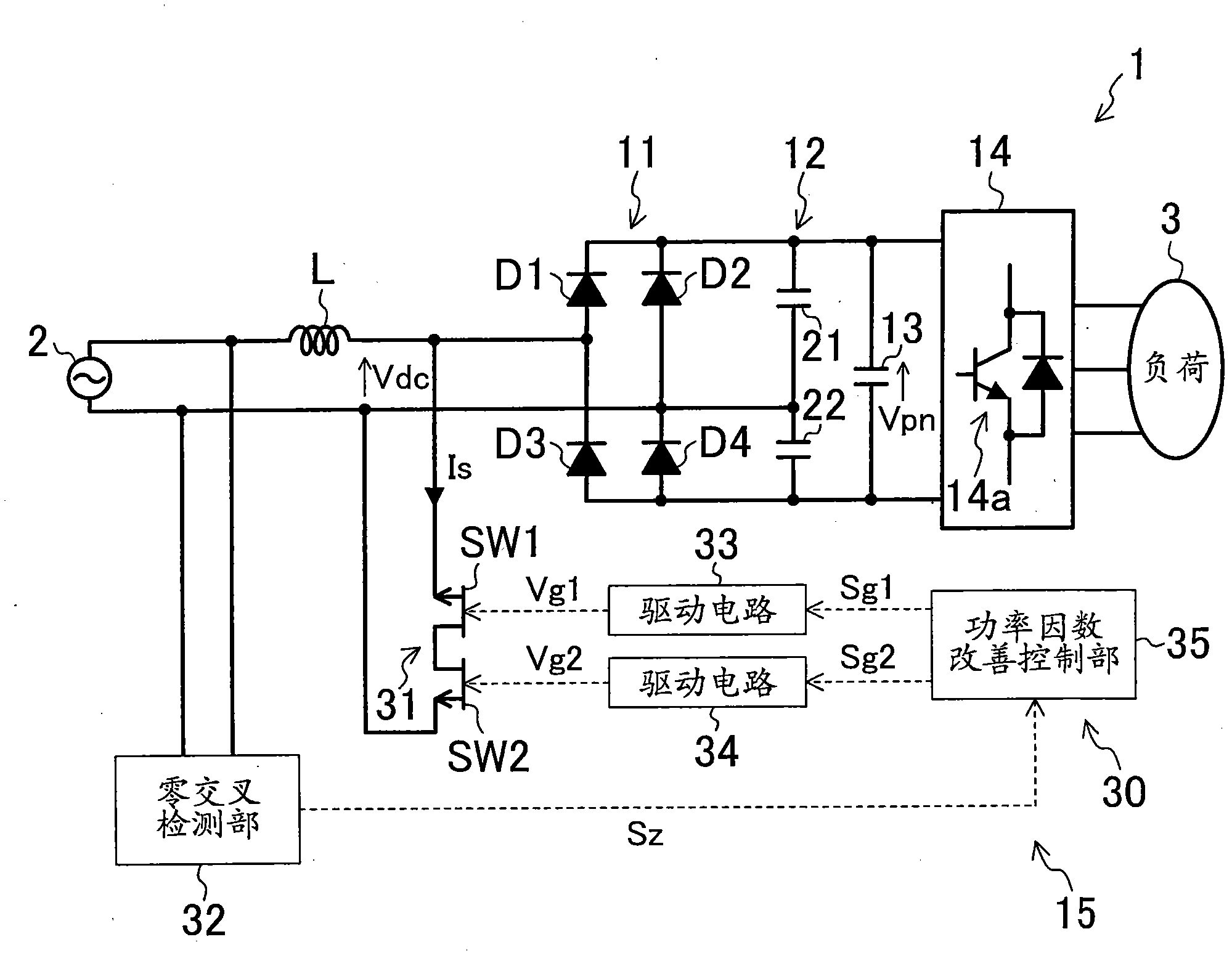
[0062] figure 1 An example of a circuit of the power conversion device 1 according to the first embodiment of the present invention is shown in . This power conversion device 1 includes an AC-DC conversion circuit 11, a voltage doubler circuit 12, a smoothing capacitor 13, a DC-AC conversion circuit 14, and a power factor improvement circuit 15, and is configured to convert the AC voltage supplied from the AC power supply 2 into a predetermined frequency. The voltage is supplied to loads such as three-phase AC motors.

[0063] The AC-DC conversion circuit 11 is connected to the AC power source 2 and configured to rectify the AC voltage into DC. This AC-DC conversion circuit 11 is composed of multiple ( Figure 4 In the example, four) diodes D1-D4 are connected in a bridge-type diode bridge circuit, and are connected to the AC power source 2 via a reactance coil (L). Thus, the AC voltage of the AC power source 2 is converted into a DC voltage by the bridge circuit of the dio...

no. 2 approach

[0113] —Overall composition—

[0114] Figure 11 A schematic configuration of the power conversion device 60 according to the second embodiment of the present invention is shown in . The power conversion device 60 directly converts the AC power obtained from the AC power source 61 of a certain frequency into AC power of another frequency, which is a so-called matrix AC-AC converter (matrix converter).

[0115] The matrix AC-AC converter 60 includes a plurality of (six in the illustrated example) bidirectional switches Sur, Sus, Sut, Svr, Svs, Svt as switch parts. In addition, the Figure 11 In the example, the matrix AC-AC converter 60 is configured to convert the AC power output from the three-phase AC power supply 61 into a single-phase current to supply the load 62 such as a motor, but it is not limited thereto, for example, it can also be a three-phase The AC power of the AC power supply 61 may be any other configuration such as a configuration in which the AC power is ...


PUM


Abstract

Provided is a bidirectional switch circuit wherein two switching elements are electrically connected in two directions. Out of the two switching elements (SW1, SW2) connected in series, the switching element (SW1) wherein a reverse direction voltage higher on the source (S1) side than that on the drain (D) side is applied, is configured such that a current can be carried from the source (S1) side to the drain (D) side, even in a state where ON drive signals are not inputted to a gate terminal (G1).

Description

technical field [0001] The invention relates to a bidirectional switch circuit in which two switching elements are connected in series to be capable of bidirectional conduction. Background technique [0002] Conventionally, a bidirectional switch circuit configured by connecting two switching elements so as to conduct in both directions has been known. Such bidirectional switch circuits, as disclosed in Patent Documents 1 and 2, are provided with switching elements such as IGBTs or MOSFETs that are provided with anti-parallel diodes, and the anti-parallel diodes are connected in opposite directions to each other, or a pair of anti-blocking diodes are connected to each other. The IGBTs are connected in reverse parallel with each other. [0003] Such a bidirectional switch circuit is used, for example, in a switch circuit of a matrix AC-AC converter disclosed in Patent Document 2, a power factor improvement circuit of a power conversion circuit disclosed in Patent Document 3,...

Claims


Application Information

Patent Timeline
IPC IPC(8): H02M1/08
CPCY02B70/126H02M5/458H02M1/4208H03K17/664H03K17/6874H03K17/74H03K2217/0009H03K2217/0081H02M3/33576Y02B70/10
Inventor 川嶋玲二久山和志日比野宽关本守满前田敏行松野澄和
Owner DAIKIN IND LTD
Why Eureka
Try Eureka