
Replaceable lubricating oil applying device for bearing

A technology for applying lubricating oil and bearings, applied in the direction of engine lubrication, lubricating parts, engine components, etc., can solve the problems of increasing equipment investment costs, wasting lubricating oil, and restricting usability, saving economic costs and reducing labor intensity. , The effect of preventing external splashing

Active Publication Date: 2015-10-28
XINCHANG COUNTY SANHE BEARING
View PDF5 Cites 19 Cited by
  • Summary
  • Abstract
  • Description
  • Claims
  • Application Information

AI Technical Summary

Problems solved by technology

[0002] After the bearing is processed and assembled, lubricating oil will be applied between the inner ring and the outer ring of the bearing before packaging. The purpose is to prevent the bearing from rusting during storage, and it is also convenient for users to apply immediately. The oil nozzle sprays oil between the inner ring and the outer ring, and achieves the purpose of fuel saving through the method of precise oil injection. After the oil is applied and rotated, some excess oil will overflow, so the bearing often needs to be correspondingly oiled after oiling. The equipment wipes off the excess oil, which not only wastes the lubricating oil, but also increases the investment cost of the equipment, and each time the bearings are oiled one by one, which is inefficient and labor-intensive. At present, some oiling machines only One type of bearing can be painted, but the usability is greatly limited, and the economy is very poor

Method used


Image

  • Replaceable lubricating oil applying device for bearing
  • Replaceable lubricating oil applying device for bearing
  • Replaceable lubricating oil applying device for bearing

Examples


Embodiment Construction

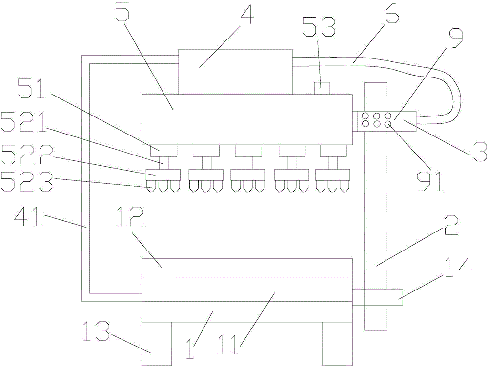
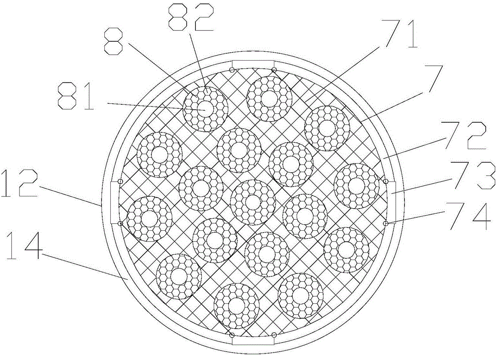
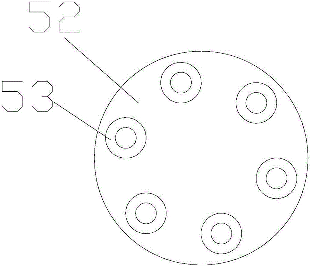
[0017] refer to figure 1 , figure 2 , image 3 and Figure 4 , a replaceable lubricating device for bearings of the present invention, comprising an oiling tank 1, a sliding rod 2, a sliding sleeve 3, a negative pressure fan and a power supply room 4, an oil storage tank 5, a ventilation pipe 41 and a bearing placement plate 7, Oil tank 1 is also provided with oil return tank 11, oil baffle plate 12, supporting foot 13 and support bar 14, and oil return tank 11 is positioned at the middle position of oil tank 1, and oil baffle plate 12 is positioned at the top of oil return tank 11, and leg 13 supports oil tank 1 , the supporting rod 14 is located on one side of the oil tank 1, one end of the sliding rod 2 is fixedly connected to the supporting rod 14, the sliding sleeve 3 is slidably placed on the sliding rod 2, one side of the sliding sleeve is fixedly connected to the oil storage tank 5, and the upper end of the oil storage tank 5 is fixed There is a negative pressure f...


PUM


Abstract

The invention provides a replaceable lubricating oil applying device for a bearing. The replaceable lubricating oil applying device comprises a lubricating oil applying box, a sliding rod, a sliding sleeve, a negative-pressure fan and power source chamber, an oil storing box, a ventilating pipe and a bearing placing plate. The replaceable lubricating oil applying device disclosed by the invention can limit the movements of the bearing, and avoids the situation that the position of the bearing is changed in the lubricating oil applying process, so that the lubricating oil applying is non-uniform; an oil outlet pipe rotates applying the lubricating oil, so that the lubricating oil applying is uniform, environmental pollution caused by the outside splashing of the lubricating oil can be avoided, the redundant lubricating oil returns to an oil returning box through grid holes and oil leaking holes, the recovery of the redundant lubricating oil is realized, and the cost is greatly reduced; the replaceable lubricating oil applying device disclosed by the invention is simple in structure, a plurality of the bearings can be applied at the same time because a plurality of bearing placing blocks are arranged, so that the operating efficiency is improved in multiples, the economic cost is reduced, and the labor intensity of a worker is alleviated; the lubricating oil applying device is replaceable and can apply the bearings in different types and sizes, so that the economic benefits are good.

Description

【Technical field】 [0001] The invention relates to the technical field of bearing lubrication, in particular to the technical field of a replaceable bearing lubricating oil device. 【Background technique】 [0002] After the bearing is processed and assembled, lubricating oil will be applied between the inner ring and the outer ring of the bearing before packaging. The purpose is to prevent the bearing from rusting during storage, and it is also convenient for users to apply immediately. The oil nozzle sprays oil between the inner ring and the outer ring, and achieves the purpose of fuel saving through the method of precise oil injection. After the oil is applied and rotated, some excess oil will overflow, so the bearing often needs to be correspondingly oiled after oiling. The equipment wipes off the excess oil, which not only wastes the lubricating oil, but also increases the investment cost of the equipment, and each time the bearings are oiled one by one, which is inefficie...

Claims


Application Information

Patent Timeline
IPC IPC(8): F16N7/40F16N21/02F16N31/02
CPCF16N7/40F16N21/02F16N31/02
Inventor 张军吕甲红
Owner XINCHANG COUNTY SANHE BEARING
Learn More