Air duct machine with detachable draining pump located at middle partition board and air conditioner

A technology of drainage pump and air duct machine, which is applied in air conditioning system, prevention of condensate water, space heating and ventilation, etc., can solve problems such as difficulty in operation of air duct machine water pump components, and achieve the effect of solving difficult operation.

Inactive Publication Date: 2015-10-28
GD MIDEA HEATING & VENTILATING EQUIP CO LTD +1
View PDF6 Cites 6 Cited by
  • Summary
  • Abstract
  • Description
  • Claims
  • Application Information

AI Technical Summary

Problems solved by technology

[0005] The beneficial effects of the present invention are: a detachable fixed drainage pump assembly is adopted in the housing of the air duct machine, and the water receiving tray is communicated with the outside through the drainage pump assembly, so that the condensed water in the water receiving tray can be discharged in time, and when maintenance is required When it is used, the water pump assembly can be directly removed from the middle partition, and the drain end of the drainage pump assembly can be pulled out from the outlet pipe of the drainage pump, which solves the problem of difficult operation of the water pump assembly of the air duct machine on site.

Method used


Image

  • Air duct machine with detachable draining pump located at middle partition board and air conditioner
  • Air duct machine with detachable draining pump located at middle partition board and air conditioner
  • Air duct machine with detachable draining pump located at middle partition board and air conditioner

Examples


Embodiment Construction

[0029] The principles and features of the present invention are described below in conjunction with the accompanying drawings, and the examples given are only used to explain the present invention, and are not intended to limit the scope of the present invention.

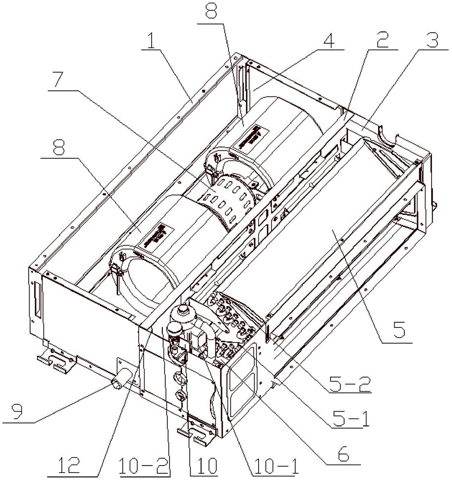
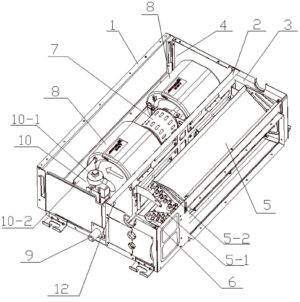
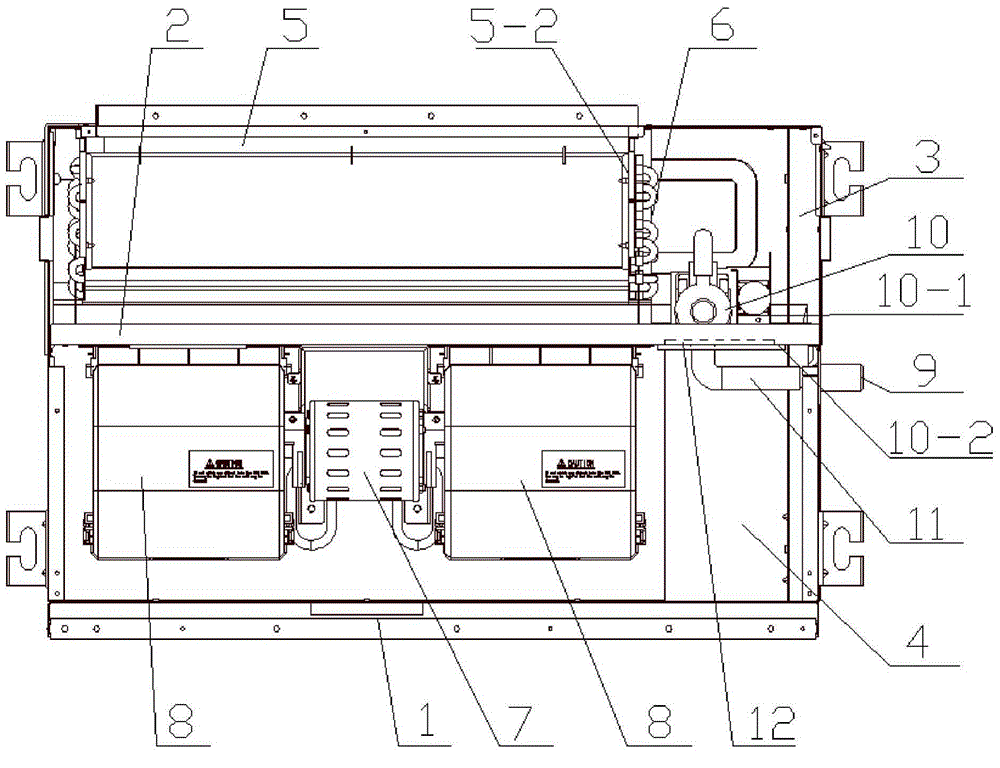
[0030] like figure 1 , image 3 As shown, the present invention includes an air duct machine housing 1, the air duct machine housing 1 is provided with a middle partition 2, and the middle partition 2 separates the air duct machine housing into a heat exchange chamber 3 and a A fan chamber 4, a heat exchanger 5 is provided in the heat exchange chamber 3, and a water receiving tray 6 for collecting condensed water dripping from the heat exchanger 5 is provided below the heat exchanger 5. The fan cavity 4 is provided with a motor assembly 7 and a wind wheel volute assembly 8, the output shaft of the motor assembly 7 is connected with the wind wheel of the wind wheel volute assembly 8 and used to drive the wind wheel ...


PUM


Abstract

The invention relates to an air duct machine with a detachable draining pump located at a middle partition board and an air conditioner. The air duct machine comprises an air duct machine shell. The air duct machine shell is internally provided with the middle partition board. The middle partition board divides the air duct machine shell into a heat exchange cavity and a draught fan cavity. The heat exchange cavity is internally provided with a heat exchanger. A water pan is arranged below the heat exchanger. The draught fan cavity is internally provided with a motor assembly and a wind turbine volute assembly. The air outlet end of the wind turbine volute assembly penetrates through the middle partition board and faces the heat exchanger. The air duct machine shell is provided with a draining pump water outlet connecting pipe. The middle partition board is provided with a detachable draining pump assembly. The water inlet end of the draining pump assembly is communicated with the interior of the water pan. The draining end of the draining pump assembly is communicated with the draining pump water outlet connecting pipe. The draining pump assembly is detachably fixed in the air duct machine shell. When the air duct machine needs to be maintained, the draining pump assembly is directly dismantled from the middle partition board, and the draining end of the draining pump assembly is removed from the draining pump water outlet connecting pipe; the problem that a water pump assembly of an existing air duct machine is difficult to maintain on site is solved.

Description

technical field [0001] The invention relates to the technical field of air duct machine equipment, in particular to a detachable air duct machine and an air conditioner in which a drainage pump is located on a middle partition. Background technique [0002] The existing commonly used air duct machine is installed inside the ceiling, and the drainage pump assembly is fixed on the left or right side plate of the air duct machine. If the water pump assembly needs to be repaired or replaced, a certain space must be reserved on the side before installation. Wide maintenance space. For some installation locations, due to the limited installation space, it is not possible to reserve enough space for maintenance and replacement of the water pump. The whole unit can only be removed or the ceiling is damaged, and the whole unit can only be removed for maintenance. There are many restrictions, and the actual operation is very difficult. Contents of the invention [0003] The technic...

Claims


Application Information

Patent Timeline
Patent Type & Authority Applications(China)
IPC IPC(8): F24F1/00F24F13/30F24F13/22
CPCF24F1/0007F24F13/222F24F13/30
Inventor 刘纯王鹏
Owner GD MIDEA HEATING & VENTILATING EQUIP CO LTD
Why Eureka
Try Eureka