Improved method for detecting short trouble of exciting winding of turbonator

A technology of turbogenerator and excitation winding, which is applied in the direction of motor generator testing, measuring electricity, measuring devices, etc. It can solve the problems of increased calculation error of the theoretical value of excitation current, insufficient sensitivity, and unsatisfactory linearity, etc., and achieves improvement. The effect of detection accuracy

Active Publication Date: 2015-10-28
NORTH CHINA ELECTRIC POWER UNIV (BAODING)
View PDF7 Cites 10 Cited by
  • Summary
  • Abstract
  • Description
  • Claims
  • Application Information

AI Technical Summary

Problems solved by technology

The disadvantage of this method is that when a slight short-circuit fault occurs in the excitation winding of the turbogenerator, the deviation between the theoretical value of the excitation current and the actual value is not large. There is a direct proportional relationship between the no-load electromotive force and the excitation current during operation. In fact, the linearity between the two is not ideal, which leads to an increase in the calculation error of the theoretical value of the excitation current. Diagnosis System (RDST) User Manual "When using the excitation current method to diagnose the short circuit fault of the excitation winding, the diagnostic threshold is set to 5%, and only when the deviation between the theoretical value of the excitation current and the actual value exceeds 5% can it be determined that there is a short circuit between turns of the rotor failure, its sensitivity is clearly insufficient

Method used


Image

  • Improved method for detecting short trouble of exciting winding of turbonator
  • Improved method for detecting short trouble of exciting winding of turbonator
  • Improved method for detecting short trouble of exciting winding of turbonator

Examples


Embodiment Construction

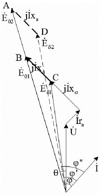
[0038] The electromotive force vector diagram of the turbogenerator in a certain operating state (active power P, reactive power Q) is as follows: figure 1 Shown in the solid line. According to the vector diagram, the expression can be obtained:

[0039]

[0040] According to expression (1), it can be further obtained:

[0041]

[0042] According to formula (2), the electromagnetic power of the generator can be known as:

[0043]

[0044] It is now assumed that when the excitation current of the generator is increased, the stator side θ, The equivalence remains unchanged, and the no-load electromotive force is given by increased to Translate the line segment BC to AD in the figure to determine the air gap electromotive force of the generator can be seen compare significantly increased, and angle of also greater than and angle of The following expressions exist:

[0045]

[0046] Further get:

[0047] P M1 M2 (5)

[0...


PUM


Abstract

The invention discloses an improved method for detecting short trouble of an exciting winding of a turbonator. The method comprises the following steps: A, obtaining parameters and a characteristic curve of the turbonator; B, establishing a two-dimensional numerical simulation model, performing calculation to obtain a stator current loading value, and applying a relatively small initial value If1 to the exciting winding to calculate the electromagnetic torque TM1'; C, keep the stator three-phase current loading value constant, circularly increasing the exciting current by taking [delta]If as an interval, and calculating the electromagnetic torque to obtain an array of (Ifi, Tmi'); D, performing quadratic function fitting of the array to obtain a function of TM'=f(If); E, calculating an actual value of the electromagnetic torque of the electric generator; F, allowing TM=TM' to solve an exciting current value; G, circularly changing P and Q values, and calculating If at each working condition; H, forming a three-dimensional latticed surface by using If, P, and Q to calculate If at any working condition; and I, comparing the exciting current value resulting from the step H with a measured value to judge if trouble comes. According to the method, defects in the prior art are overcome, and the detection sensitivity of an exciting current method is improved.

Description

technical field [0001] The invention relates to the technical field of turbogenerators, in particular to an improved on-line detection method for short-circuit faults of excitation windings of turbogenerators. Background technique [0002] Excitation winding short circuit is a common turbogenerator fault, and it has a growing trend in my country in recent years. Experience has shown that minor turn-to-turn faults in the rotor winding will not have a serious impact on the generator, and the fault characteristics are not significant, making the fault hidden; however, if the fault is not dealt with in a timely and effective manner, it may further develop and Especially when there is a strong negative-sequence magnetic field in the generator, the current flowing through the inter-turn short-circuit point is relatively large, which may lead to further deterioration of the fault and pose a greater threat to the safe and stable operation of the unit itself. [0003] Excitation win...

Claims


Application Information

Patent Timeline
Patent Type & Authority Applications(China)
IPC IPC(8): G01R31/06G01R31/34
Inventor 武玉才李永刚张嘉赛
Owner NORTH CHINA ELECTRIC POWER UNIV (BAODING)
Why Eureka
Try Eureka