Touch panel

A touch panel and touch sensing layer technology, applied in the direction of instruments, electrical digital data processing, data processing input/output process, etc., can solve the problems of poor visual effect of the touch panel and affecting the beauty of the touch panel, etc.

Inactive Publication Date: 2015-10-28
INNOLUX CORP
View PDF3 Cites 4 Cited by
  • Summary
  • Abstract
  • Description
  • Claims
  • Application Information

AI Technical Summary

Problems solved by technology

[0003] Touch panels can be roughly divided into resistive touch and capacitive touch technologies. At present, capacitive touch is the main technology. Capacitive touch technology usually forms a touch sensing element by patterning a transparent electrode layer. Due to the limitations of the coating temperature and the design of the

Method used


Image

  • Touch panel
  • Touch panel
  • Touch panel

Examples


Embodiment Construction

[0030] The structural design and manufacturing method of some embodiments of the touch panel of the present invention are described in detail below. However, it can be understood that the inventive concept provided by the present invention can be implemented in a wide variety of backgrounds. The specific implementation discussed here The examples are only used to illustrate specific ways of making and using some embodiments of the present invention, and are not intended to limit the scope of the present invention.

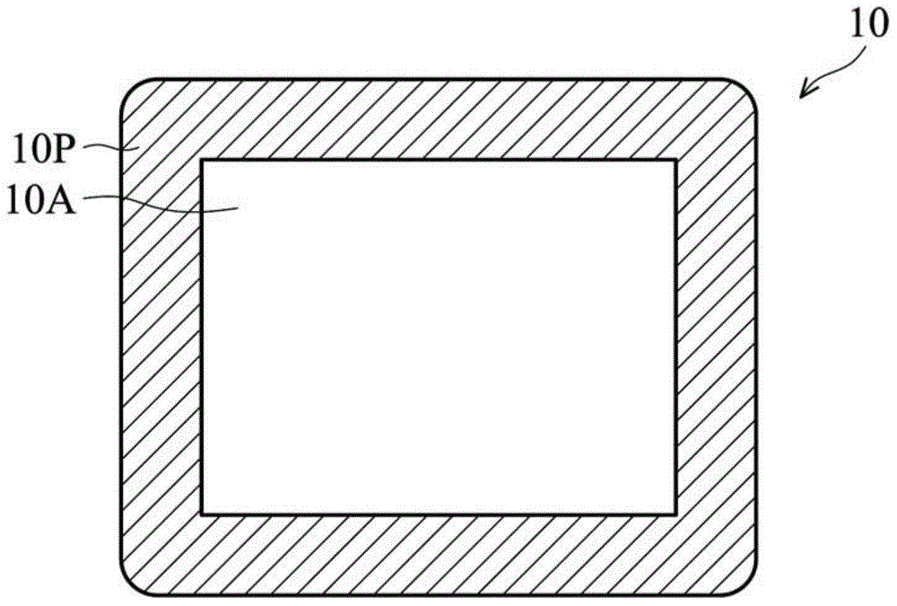
[0031] Such as figure 1 As shown, the touch panel 10 can be divided into an active area 10A and a peripheral area 10P surrounding the active area 10A. The touch sensing element is formed in the active area 10A, and the peripheral area 10P forms a decorative layer with a light-shielding effect. figure 1 A schematic plan view showing a touch panel 10 without the dielectric material layer of the present invention, since the conductive material forming the touch sensin...


PUM


Abstract

The present invention discloses a touch panel, comprising a protective cover plate and a display element below the protection cover. A touch sensing layer is disposed in an active area of the touch panel, and between the protective cover plate and the display element. A decorative layer is provided in a peripheral region of the touch panel, and between the protective cover plate and the display element. The peripheral region surrounds the active area. The touch panel also comprises a dielectric material layer between the protective cover plate and the display element. A reflectivity difference between the active area and the surrounding region is between 0 and 0.5.

Description

technical field [0001] The invention relates to a touch panel, in particular to a structural design for adjusting the appearance color of the touch panel and a manufacturing method thereof. Background technique [0002] With the development of the electronic industry, in recent years, various digital products, such as mobile phones, tablet computers, digital cameras and other electronic products have the demand for touch function. Using touch panels in these electronic products can provide more convenient and fast Operation method. [0003] Touch panels can be roughly divided into resistive touch and capacitive touch technologies. At present, capacitive touch is the main technology. Capacitive touch technology usually forms a touch sensing element by patterning a transparent electrode layer. Due to the limitations of the coating temperature and the design of the integrated circuit, the transparent electrode layer requires a higher film thickness to meet the resistance requi...

Claims


Application Information

Patent Timeline
IPC IPC(8): G06F3/041G06F3/044
Inventor 杨礎豪陈柏宇骆建桦李家欣姚怡安
Owner INNOLUX CORP
Why Eureka
Try Eureka