New type low voltage power transmission cable

A transmission cable and low-voltage technology, which is applied in the field of new low-voltage transmission cables, can solve problems such as affecting service life and multiple faults of cables, and achieve the effects of shielding electromagnetic interference, improving adaptability, and improving stability

Inactive Publication Date: 2015-10-28
STATE GRID SHANDONG ELECTRIC POWER +1
View PDF9 Cites 5 Cited by
  • Summary
  • Abstract
  • Description
  • Claims
  • Application Information

AI Technical Summary

Problems solved by technology

The general voltage of residential and factory electricity is 220-380V, because the cables used are rarely exposed to the ground, and most of them are located in underground pipelines. Traditional cables have not taken this into consideration in the design, resulting in relatively large cables during use. Many failures, or affect the service life due to the influence of the environment

Method used


Image

  • New type low voltage power transmission cable

Examples


Embodiment 1

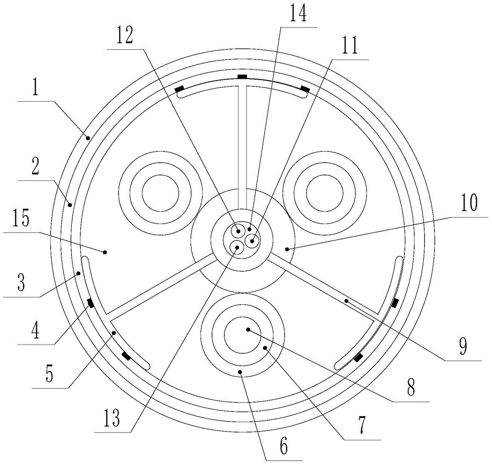
[0017] Embodiment 1: A new type of low-voltage power transmission cable, including a conductor 8, and also includes a supporting frame, a flame-retardant layer 3, an armor layer 2, and a water-blocking layer 1, wherein the outer surface of the conductor 8 is covered with an insulating layer 7, The insulating layer 7 is covered with a shielding layer 6, and the supporting frame includes a hollow cavity 14, a supporting bracket 9 and an arc frame 5, and the conductor 8 is located in the filler 15 between adjacent supporting brackets 9; the hollow cavity 14 and the shielding layer 6 are provided with a buffer layer 10; the flame-retardant layer 3 is arranged on the outside of the arc-shaped frame 5 supporting the skeleton, and an armored layer 2 is arranged on the outer side of the flame-retardant layer 3, and the outer side of the armored layer 2 A water blocking layer 1 is provided.

Embodiment 2

[0018] Embodiment 2: A new type of low-voltage power transmission cable, including a conductor 8, and also includes a supporting frame, a flame-retardant layer 3, an armor layer 2, and a water-blocking layer 1, wherein the outer surface of the conductor 8 is covered with an insulating layer 7, The insulating layer 7 is covered with a shielding layer 6, and the supporting frame includes a hollow cavity 14, a supporting bracket 9 and an arc frame 5, and the conductor 8 is located in the filler 15 between adjacent supporting brackets 9; the hollow cavity 14 and the shielding layer 6 are provided with a buffer layer 10; the flame-retardant layer 3 is arranged on the outside of the arc-shaped frame 5 supporting the skeleton, and an armored layer 2 is arranged on the outer side of the flame-retardant layer 3, and the outer side of the armored layer 2 A water blocking layer 1 is provided. The filler 15 is composed of the following ingredients in parts by weight: 25-35 parts of high-d...


PUM


Abstract

The invention discloses a new type low voltage power transmission cable which belongs to the technical field of power transmission cables. The transmission cable is used for the construction of underground routes of a residential place or a factory. The cable comprises conductors, a support framework, a fire retardant layer, an armor layer, and a water resisting layer. The conductors are wrapped in insulation layers. The insulation layers are wrapped in shielding layers. The support framework comprises support frames and bow shaped frames. The conductors are located in the filler between the adjacent support frames. Between the hollow cavity and the shielding layers is a buffering layer. The fire retardant layer is arranged at the outer side of the bow shaped frames of the support framework. The outer side of the fire retardant layer is provided with the armor layer. The outer side of the armor layer is provided with the water resisting layer. With such technical schemes, the cable of the invention can effectively help resolve various problems arising from the laying of underline pipes and the service lifetime of the cable can be effectively prolonged.

Description

technical field [0001] The invention belongs to the field of power transmission lines, and in particular relates to a novel low-voltage power transmission cable. Background technique [0002] With the development of science and technology, electricity plays an increasingly important role in residents' life and production activities. The general voltage of residential and factory electricity is 220-380V, because the cables used are rarely exposed to the ground, and most of them are located in underground pipelines. Traditional cables have not taken this into consideration in the design, resulting in relatively large cables during use. Many failures, or affect the service life due to the influence of the environment. Contents of the invention [0003] The purpose of the present invention is to provide a new type of low-voltage power transmission cable, which can effectively adapt to many problems existing in the process of laying underground pipelines, and can effectively i...

Claims


Application Information

Patent Timeline
Patent Type & Authority Applications(China)
IPC IPC(8): H01B9/02H01B7/285H01B7/29
CPCY02A30/14
Inventor 林冰陈晓民尹祥田徐明志屈守山
Owner STATE GRID SHANDONG ELECTRIC POWER
Why Eureka
Try Eureka