Manufacturing method of clamp for turning end faces

A production method and end face technology, applied in the direction of the chuck, etc., can solve the problems of the parallelism easily exceeding the tolerance range and the parallelism difference.

Inactive Publication Date: 2015-11-04
潘秀兰
View PDF5 Cites 1 Cited by
  • Summary
  • Abstract
  • Description
  • Claims
  • Application Information

AI Technical Summary

Problems solved by technology

However, since the end faces of the three jaws of the three-jaw self-centering chuck (especially the chuck that has been used for a long time) cannot b

Method used


Image

  • Manufacturing method of clamp for turning end faces
  • Manufacturing method of clamp for turning end faces

Examples


Embodiment Construction

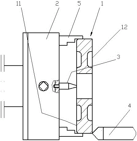
[0012] The specific implementation of the present invention will now be described with reference to the drawings, taking the processing of the end face of the gear blank workpiece as an example.

[0013] The method of the present invention includes the following steps:

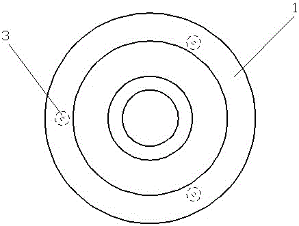
[0014] 1. Remove the claw 5 on the three-jaw self-centering chuck 2, and machine the screw holes on the end surface of the three-jaw self-centering chuck, and the screw holes are in the circumferential direction on the end surface of the three-jaw self-centering chuck Set symmetrically, the number of screw holes is 3;

[0015] 2. Tighten the positioning columns 3 into the screw holes respectively, start the lathe positioning column to rotate with the three-jaw self-centering chuck, and turn the annular surface formed by the endpoints of the positioning column so that the endpoints of the positioning column are on the same plane , The positioning column protrudes from the three-jaw self-centering chuck and can contac...


PUM

PropertyMeasurementUnit
Diameteraaaaaaaaaa

Abstract

The invention discloses a manufacturing method of a clamp for turning end faces. The manufacturing method comprises the steps that 1, clamping claws on a three-claw self-centering chuck are taken down, and three screw holes are formed in the end face of the three-claw self-centering chuck and symmetrically distributed on the end face of the three-claw self-centering chuck in the circumferential direction; and 2, positioning columns are screwed in the screw holes respectively, the lathe positioning columns are started to rotate along with the three-claw self-centering chuck for turning a face formed by the end points of the positioning columns, the end points of the positioning columns are made to be on the same plane, and the positioning columns extend out of the three-claw self-centering chuck and can make contact with the first end face of a workpiece. The manufacturing method is convenient to implement, and the manufactured clamp can ensure the depth of parallelism between the two end faces of the turned workpiece.

Description

Technical field [0001] The invention relates to a manufacturing method of a clamp for turning the end face of a workpiece. The clamp is used for clamping the workpiece whose end faces at both ends have parallelism requirements. Background technique [0002] The traditional steps of machining gear blank workpieces on ordinary lathes are generally to clamp the gear blank on a three-jaw self-centering chuck and first turn the outer circle, hole and end face of the gear blank (such as figure 1 Show the first end surface 11), and then turn the other end surface of the gear blank (such as figure 2 As shown in the second end surface 12), the end surface of the claw on the three-jaw self-centering chuck serves as the positioning reference surface for the other end surface of the turning gear blank. However, since the end faces of the three jaws of the three-jaw self-centering chuck (especially the chuck that has been used for a long time) cannot be on the same plane, the parallelism of ...

Claims


Application Information

Patent Timeline
IPC IPC(8): B23B31/103
CPCB23B31/103
Inventor 潘秀兰
Owner 潘秀兰
Why Eureka
Try Eureka