
A solvent recovery system for dmf salty wastewater

A salt-containing wastewater, recovery system technology, applied in alkali metal halide purification, organic chemistry, carboxylic acid amide separation/purification, etc., can solve the problems of equipment corrosion, rectification tower blockage, cumbersome pre-treatment and post-treatment processes, etc. , to achieve the effect of simple process and low energy consumption

Active Publication Date: 2017-01-11
TIANJIN UNIV
View PDF7 Cites 0 Cited by
  • Summary
  • Abstract
  • Description
  • Claims
  • Application Information

AI Technical Summary

Problems solved by technology

DMF is easily decomposed into formic acid and dimethylamine when heated under acidic or alkaline conditions. The existence of formic acid and dimethylamine will seriously affect the quality of DMF products and cause serious corrosion to equipment
Therefore, before treating DMF wastewater, acid or alkali is often used to neutralize DMF wastewater into neutrality, and then follow-up treatment will produce salt during the neutralization process. For the treatment of low-concentration salt-containing DMF wastewater, rectification is used. method can lead to problems such as distillation column blockage
[0003] Patent CN200510061857.5 discloses a three-effect recovery method containing DMF wastewater, and patent CN201310304564.X discloses a four-effect rectification recovery method containing DMF wastewater. Although these methods greatly save the recovery energy consumption of DMF wastewater, but The tower plugging problem of salt in DMF wastewater is not considered
Patent CN200820120577.6 discloses a treatment device before rectification of DMF recovered liquid, and patent CN201320014613.1 discloses a DMF wastewater recovery residue evaporator. These patents consider the problem of tower blockage of salt in DMF wastewater, but the pretreatment And the post-processing process is cumbersome, and the investment and energy consumption of industrial equipment are relatively large

Method used


Image

  • A solvent recovery system for dmf salty wastewater
  • A solvent recovery system for dmf salty wastewater
  • A solvent recovery system for dmf salty wastewater

Examples


Embodiment 1

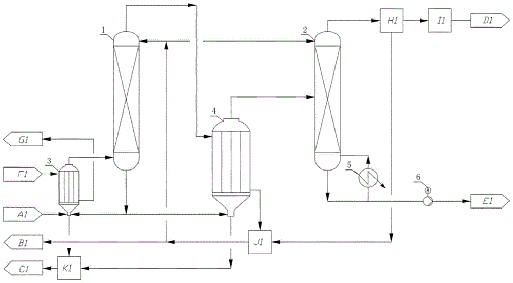
[0023] A kind of solvent recovery system of DMF saline waste water (see figure 1 ) comprises a first-effect evaporator 3, a first-effect rectification tower 1, a second-effect evaporator 4 and a second-effect rectification tower 2, the feed port at the bottom of the first-effect evaporator 3 is connected to DMF saline waste water A1, and the first-effect evaporator 3 The outlet at the top of the top is connected to the bottom of the first-effect rectification tower 1 through pipelines, and the bottom of the first-effect rectification tower 1 is connected to the bottom of the first-effect evaporator 3 and the second-effect evaporator 4 through pipelines respectively, and the first-effect rectification The top of tower 1 passes through the second-effect evaporator 4 through the pipeline and is connected to the reflux system J1; the upper part of the first-effect evaporator 3 is connected to the heat source F1 through the pipeline, and the lower part of the first-effect evaporator...

Embodiment 2

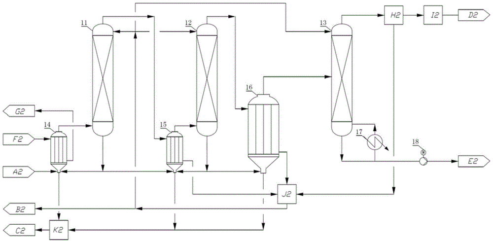
[0027] The solvent recovery system of the second DMF saline wastewater (see figure 2 ), comprising one-effect evaporator 14, one-effect rectifying tower 11, two-effect evaporator 15, two-effect rectifying tower 12, three-effect evaporator 16, three-effect rectifying tower 13, the inlet at the bottom of one-effect evaporator 14 The feed port is connected to the DMF saline waste water A2, and the outlet at the top of the first-effect evaporator 14 is connected to the bottom of the first-effect rectification tower 11 through a pipeline, and the bottom of the first-effect rectification tower 11 is respectively connected to the first-effect evaporator 14 through a pipeline. It is connected with the bottom of the second-effect evaporator 15, and the top of the first-effect rectification tower 11 is connected with the reflux system J2 after passing through the second-effect evaporator 15 through a pipeline; the upper part of the first-effect evaporator 14 is connected with the heat s...

Embodiment 3

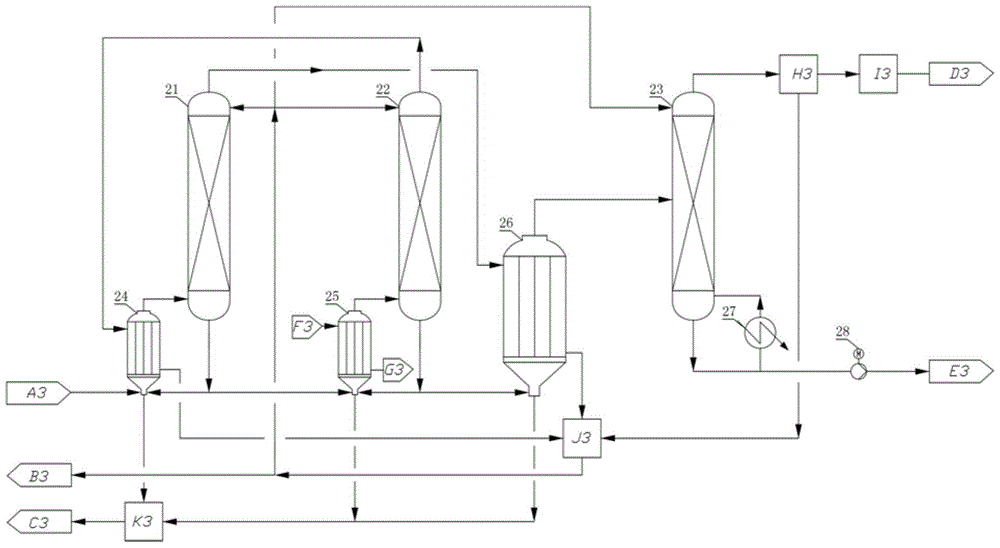
[0031] The solvent recovery system of the third DMF saline wastewater (see image 3 ), comprising one-effect evaporator 24, one-effect rectifying tower 21, two-effect evaporator 25, two-effect rectifying tower 22, three-effect evaporator 26, three-effect rectifying tower 23, the inlet at the bottom of one-effect evaporator 24 The feed port is connected to the DMF saline waste water A3, and the outlet at the top of the first-effect evaporator 24 is connected to the bottom of the first-effect rectification tower 21 through a pipeline, and the bottom of the first-effect rectification tower 21 is respectively connected to the first-effect evaporator 24 through a pipeline. It is connected with the bottom of the second-effect evaporator 25, and the top of the first-effect rectification tower 21 is connected with the reflux system J3 after passing through the three-effect evaporator 26 through a pipeline; the top of the second-effect evaporator 25 is connected with the second-effect r...


PUM


Abstract

The invention discloses a solvent recovering system for DMF (Dimethyl Formamide) saliferous wastewater. An evaporating and rectifying system is formed through combining a plurality of evaporators and rectifying towers, and a reboiler, a cooling system, a reflux system, a negative pressure system and a salt yielding system are disposed correspondingly; the recovering system disclosed by the invention is adopted to treat the DMF saliferous wastewater; top steam of the rectifying tower of a corresponding previous effect serves as a heat source of the evaporator of the rectifying tower of a corresponding next effect through setting the operating pressure of the rectifying tower of each effect, so as to use the condensation heat energy of steam of the corresponding previous effect; and the system disclosed by the invention combines the evaporators and the rectifying towers, so that the problem of tower blockage during the rectification of the DMF saliferous wastewater can be solved, the process is simple, the energy consumption is low, and high-purity salt and a DMF product can be obtained. The volume of steam consumed by the solvent recovering system for the DMF saliferous wastewater, disclosed by the invention, is 40-65% that of steam consumed during ordinary single-tower rectification.

Description

technical field [0001] The invention relates to a solvent recovery system for DMF salty wastewater. Background technique [0002] DMF, also known as N,N-dimethylformamide, is a colorless and transparent liquid that is miscible with water, alcohols, esters, ketones, ethers, unsaturated hydrocarbons and aromatic hydrocarbons, and is called a "universal solvent". , Widely used in petrochemical, organic synthesis, pharmaceutical, artificial leather and other fields, so a large amount of DMF wastewater will be produced in the chemical production process. At present, in industrial production, rectification is often used for high-concentration DMF wastewater, and multi-effect distillation is often used for low-concentration DMF wastewater. DMF is easily decomposed into formic acid and dimethylamine when heated under acidic or alkaline conditions. The existence of formic acid and dimethylamine will seriously affect the quality of DMF products and cause serious corrosion to equipmen...

Claims


Application Information

Patent Timeline
Patent Type & Authority Patents(China)
IPC IPC(8): C07C233/03C07C231/24C01D3/14
Inventor 张敏卿张金利李文鹏
Owner TIANJIN UNIV
Learn More