
Moving steel bench

A technology of gantry and steel moving, which is applied in the field of hot transfer of bar billets, can solve the problems that the steel moving gantry can not meet the requirements and the continuous casting billet has a large transverse moving span, so as to increase the steel moving distance and ensure normal operation. The effect of running and improving stability

Active Publication Date: 2017-01-25
WISDRI ENG & RES INC LTD
View PDF6 Cites 0 Cited by
  • Summary
  • Abstract
  • Description
  • Claims
  • Application Information

AI Technical Summary

Problems solved by technology

Due to the process design of the continuous casting workshop and the steel rolling workshop, sometimes the lateral movement span of the continuous casting slab is relatively large, and the general steel moving platform cannot meet the requirements

Method used


Image

  • Moving steel bench
  • Moving steel bench
  • Moving steel bench

Examples


Embodiment Construction

[0025] The following will clearly and completely describe the technical solutions in the embodiments of the present invention with reference to the accompanying drawings in the embodiments of the present invention. Obviously, the described embodiments are only some, not all, embodiments of the present invention. Based on the embodiments of the present invention, all other embodiments obtained by persons of ordinary skill in the art without making creative efforts belong to the protection scope of the present invention.

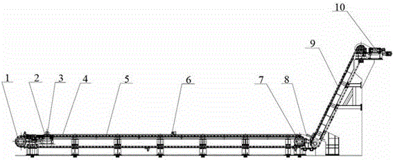
[0026] Such as figure 1 , the embodiment of the present invention provides a steel-moving platform, including a traversing frame and a lifting frame, the traversing frame and the lifting frame are connected through a steel drop channel 8, and the traversing frame is connected to the hot delivery roller of the continuous casting workshop The channel 2 cooperates to send the continuous casting slab 3 to the falling steel trough 8, and the lifting frame cooperate...


PUM


Abstract

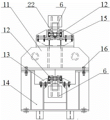
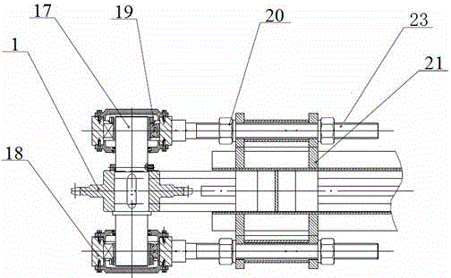
The invention relates to a steel moving rack which is a chain drive type steel moving rack. The steel moving rack comprises a transverse moving frame and a lifting frame. The transverse moving frame comprises a supporting mechanism for supporting a chain. The supporting mechanism comprises an upper supporting structure and a lower supporting structure, wherein the upper supporting structure is used for supporting the tight side of the chain, and the lower supporting structure is used for supporting the loose side of the chain. Each supporting structure comprises two rails distributed on the two sides of the chain and a guide rail located between the two rails, wherein each guide rail is located below the corresponding tight side or the corresponding loose side of the chain. Multiple groups of rolling wheels walking on the chain are evenly installed on the chain in the circumferential direction. Because the tight side and the loose side of the chain can be supported by the supper supporting structure and the lower supporting structure, the problem that due to the length of the chain, the overhung part of the chain is too long is avoided, and normal operation of the transverse moving frame is guaranteed. In this way, the steel moving rack can effectively increase the steel moving distance and is suitable for the condition that a continuous casting hot charging roller bed and a rolled steel feeding roller way for a furnace form a large span.

Description

technical field [0001] The invention belongs to the technical field of hot delivery of shaped bars and square billets, and in particular relates to a steel moving stand, which is used for transporting continuous casting hot billets into a heating furnace. Background technique [0002] At present, the hot-charging and hot-delivery process of continuous casting slabs turns steelmaking-steel rolling into a closely connected integrated production system, which can not only greatly reduce energy consumption, shorten the production cycle of products, but also improve product quality and increase metal yield. At the same time, it can reduce the floor area of ​​the factory building and save investment. In the profiled bar production line, the steel rolling system generally adopts an elevated platform, and the continuous casting billet generally adopts a hot-feeding process that first traverses and then lifts. Due to the process design of the continuous casting workshop and the stee...

Claims


Application Information

Patent Timeline
Patent Type & Authority Patents(China)
IPC IPC(8): F27D3/00
Inventor 王清秀闵威
Owner WISDRI ENG & RES INC LTD
Learn More