Spring swing life test device

A life test and crossbar technology, which is applied in the field of spring swing life test devices, can solve the problems of neglecting spring swing life and vibration device failure, and achieves the effect of reducing motion resistance and improving practicability.

Active Publication Date: 2015-11-04
ANHUI SHUCHENG HUAYUN SPRING MFG
View PDF10 Cites 2 Cited by
  • Summary
  • Abstract
  • Description
  • Claims
  • Application Information

AI Technical Summary

Problems solved by technology

[0002] The current spring tests focus on the compression and tension of the spring, but in the actual use environment, there may be cases where the spring is used to swing the elasticity, for example, the spring is used as a support for a vibrating device, and the vibrating devic

Method used


Image

  • Spring swing life test device
  • Spring swing life test device
  • Spring swing life test device

Examples


Example Embodiment

[0016] Example 1:

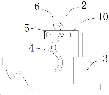
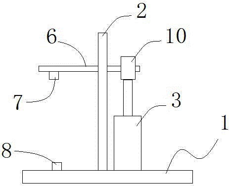
[0017] Such as figure 1 , 2 As shown, the spring swing life test device of this embodiment includes a base 1 and a bracket 2 and a cylinder 3 vertically fixed on the base 1. The bracket 2 is fixed with a horizontal block 10, and the horizontal block 10 is provided with a wavy through groove 4, A horizontal through groove 5 is fixed at the end of the piston rod of the cylinder 3; a cross rod 6 is movably installed in the horizontal through groove 5, and the cross rod 6 passes through the wavy through groove 4; One end of the rod 6 is provided with a first fixing portion 7, and the base 1 is provided with a second fixing portion 8;

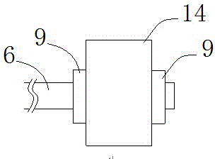
[0018] Such as image 3 As shown, the cross bar 6 is provided with an anti-drop part, the anti-drop part is composed of a cross bar 6 body and two nuts 9, the cross bar 6 body is provided with threads, the two nuts 9 are screwed on the cross bar 6 on the body, and two nuts 9 are respectively located on both sides of the horizontal th...

Example Embodiment

[0020] Example 2:

[0021] Such as Figure 4 As shown, the difference from Embodiment 1 is that the anti-dropping part in this embodiment includes the body of the cross bar 6 passing through the horizontal through slot 5 and the rollers mounted on the upper and lower sides of the body 6 through the auxiliary bracket 11 12. Two rollers 12 are provided on the upper and lower ends of the auxiliary bracket 11 to maintain balance; two sides of the roller 12 are provided with anti-falling edges 13, and the anti-falling edges 13 of the rollers 12 are stuck in the horizontal pass. Slot 5 on both sides. The anti-dropping edge 13 of the roller 12 can prevent the end of the cross bar 6 from falling out of the horizontal through groove 5, and the roller 12 can greatly reduce the movement resistance between the cross bar 6 and the horizontal through groove 5, and facilitate the roller 12 in the horizontal through groove. Move within 5.


PUM


Abstract

The present invention is to provide a spring swing life test device which is used for testing the swing life of a spring. The spring swing life test device comprises a base, a support and a cylinder, wherein the support and the cylinder are vertically and fixedly arranged on the base. The support is provided with a wavy through groove; the end portion of a piston rod of the cylinder is fixedly provided with a horizontal through groove; the horizontal through groove is internally and movably equipped with a cross bar; the cross bar passes through the wavy through groove; one end of the cross bar is provided with a first fixation portion; the base is provided with a second fixation portion; and the cross bar is provided with an anti-drop portion for preventing the cross bar from dropping out of the horizontal through groove. During test, the two ends of the spring utilize the first fixation portion and the second fixation portion respectively, and then, the cylinder is started to drive a horizontal block and the cross bar to move up and down; and meanwhile, the cross bar swings along the wavy through groove under the limitation of the wavy through groove and the horizontal through groove, thereby forcing the spring to swing while being stretched and compressed, and realizing the test of the swing life of the spring.

Description

technical field [0001] The invention belongs to the technical field of spring testing, and in particular relates to a spring swing life testing device. Background technique [0002] The current spring tests focus on the compression and tension of the spring, but in the actual use environment, there may be cases where the spring is used to swing the elasticity, for example, the spring is used as a support for a vibrating device, and the vibrating device not only has Vibration in the vertical direction, as well as swing in the horizontal direction, if only the spring force and life in the vertical direction of the spring are tested, and the swing life of the spring is ignored, it may cause premature failure of the vibration device. Therefore it is necessary to test the spring swing life. Contents of the invention [0003] The object of the present invention is to provide a spring swing life testing device for testing the spring swing life. [0004] The spring s...

Claims


Application Information

Patent Timeline
IPC IPC(8): G01M13/00
Inventor 吴基超
Owner ANHUI SHUCHENG HUAYUN SPRING MFG
Why Eureka
Try Eureka