
Wire clamp for transmission conductors

A technology for transmission wires and wire clips is applied in the field of wire clips for transmission wires, which can solve the problems of inconvenient installation and easy falling, and achieve the effects of convenient high-altitude installation, low cost and simple structure

Inactive Publication Date: 2015-11-04
姚丽
View PDF0 Cites 0 Cited by
  • Summary
  • Abstract
  • Description
  • Claims
  • Application Information

AI Technical Summary

Problems solved by technology

The disadvantage of the existing wire clip is that it is not convenient to install and it is easy to drop

Method used


Image

  • Wire clamp for transmission conductors

Examples


Embodiment Construction

[0010] An embodiment of the present invention will be described below in conjunction with the accompanying drawings.

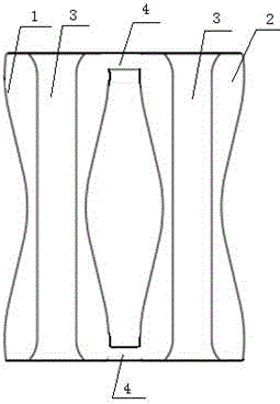
[0011] Such as figure 1 As shown, the wire clamp for power transmission wire of the present invention includes a wire clamp 1 and a wire clamp 2 2, and the wire clamp 1 and the wire clamp 2 cooperate with each other, and the wire clamp 1 and the wire clamp 2 are equipped with The groove 3 for the wires to pass through, one end of the first wire clip 1 and the second wire clip 2 are connected together through the connecting part 4, forming an integral structure. The overall structure makes the positioning between the first clamp 1 and the second clamp 2 accurate, and it is convenient for installation, just place the wire in the groove and then couple the first clamp with the second clamp, which greatly improves the work efficiency. In this embodiment, the other ends of the first wire clamp 1 and the second wire clamp 2 are also connected together through the c...


PUM


Abstract

The invention relates to a wire clamp for transmission conductors, comprising a wire clamp 1 and a wire clamp 2 which are matched with each other. The wire clamp 1 and the wire clamp 2 are respectively provided with a groove for a conductor to pass through. One end of the wire clamp 1 and one end of the wire clamp 2 are connected into a whole structure. The wire clamp of the invention is simple in structure, can be easily installed at high altitude, and is low in cost.

Description

technical field [0001] The invention relates to a clamp for power transmission wires. Background technique [0002] With the rapid development of my country's power construction, power construction technology is constantly innovating, and line power equipment with independent intellectual property rights is also emerging to adapt to the development of my country's high-voltage and extra-high voltage power construction. Clamps for power transmission wires are mainly used in overhead power lines to suspend wires, lightning protection wires or ground wires on straight pole towers by connecting fittings, and can also be used to support transposition wires on transposition towers and jumper wires on strain-resistant corner towers. fixed. The existing clamps all adopt a two-piece symmetrical structure, most of which are two-piece structures made of metal. Tighten the fastening bolts. The disadvantage of the existing wire clip is that it is not very convenient to install and it ...

Claims


Application Information

Patent Timeline
IPC IPC(8): H02G7/05
Inventor 姚丽
Owner 姚丽
Learn More