
Light control system and method

A lighting control and control terminal technology, applied in the direction of light source, electric light source, electric light circuit layout, etc., can solve the problems of restricting the promotion of the color adjustment function of ordinary lamps, troublesome installation, and high cost, and achieve the convenience of mass production, adjustment, time saving and labor saving, Easy to install effect

Inactive Publication Date: 2015-11-04
中山市城市之光灯饰电器有限公司
View PDF4 Cites 3 Cited by
  • Summary
  • Abstract
  • Description
  • Claims
  • Application Information

AI Technical Summary

Problems solved by technology

[0006] A. For the control system (DMX512, 0 to 10V dimming system, etc.), the signal line is separated from the power line, resulting in a special structure of the lamp body. In addition to the original power input line interface of the lamp itself, there must also be a signal line in and out interface, which is extremely large. Limit the popularization of the color matching function of ordinary lamps, and have disadvantages such as troublesome installation and high cost
[0007] B. Use a dedicated power carrier chip to realize high-voltage power line data transmission technology, but the price of the dedicated IC for this type of solution is relatively high, and it requires large-volume devices such as mutual inductance transformers, resulting in large volume and high cost of the terminal product, which is not suitable for the color changing needs of ordinary lamps.

Method used


Image

  • Light control system and method
  • Light control system and method
  • Light control system and method

Examples


Embodiment Construction

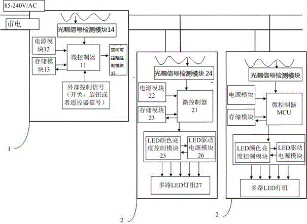
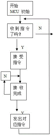
[0028] The present invention will be further described below in conjunction with the accompanying drawings and specific embodiments.

[0029] Figure 1 to Figure 4 The reference numerals in the drawings are: control terminal 1; receiving terminal 2.

[0030] Such as Figure 1 to Figure 2 As shown, a lighting control system includes a control terminal 1 and a receiving terminal 2. The control terminal 1 and the receiving terminal 2 are connected through a power line, and N receiving terminals 2 can be provided.

[0031] Such as Figure 1 to Figure 2 As shown, the control terminal 1 includes a microcontroller 11, a triac control module 15, an optocoupler signal detection module 14, a power supply module 12, a storage module 13, and an oscillation reset circuit 16. The microcontroller of the control terminal 1 The device 11 is respectively connected with the triac control module 15, the optocoupler signal detection module 14, the power module 12 and the storage module 13.

[...


PUM


Abstract

Provided in the invention is a light control system comprising a control terminal and a receiving terminal. The control terminal and the receiving terminal are connected by a power line. In addition, the invention also provides a light control system. The system and method have the following beneficial effects: the cost is low; the large-scale production can be realized conveniently; the light synchronization function of multiple lamps can be realized with low cost; installation is conveniently; and adjustment can be carried out with less time and effort.

Description

technical field [0001] The invention relates to a lighting device, in particular to a lighting control system and method in the lighting device. Background technique [0002] With the continuous advancement of technology and the continuous improvement of the quality of life, the demand for overall lighting adjustment is also increasing. Especially in the modern LED lighting system, there are more and more lamps and applications involving the color change of RGB lamps and the temperature adjustment of positive white and warm white, and a control system with simple installation and cost advantages is required to adapt. [0003] At present, to achieve synchronous color change of multiple lamps, there are mainly two kinds of wireless remote control and wired connection. [0004] 1. Wireless remote control such as WIFI, 2.4G, Bluetooth, etc. can also change the color of the lamp, but a single lamp must have a built-in receiving module, which greatly increases the cost of the la...

Claims


Application Information

Patent Timeline
Patent Type & Authority Applications(China)
IPC IPC(8): H05B37/02
Inventor 李志光甘从刚庞奉敏金敬雨
Owner 中山市城市之光灯饰电器有限公司
Learn More