
GPS synchronization controller

A technology of synchronous controller and GPS module, applied in energy-saving control technology, electrical components, electroluminescent light source, etc., can solve the problem that lamps cannot be synchronized with lighting control, and achieve the effect of improving reliability

Pending Publication Date: 2018-11-30
JIANGSU FEITIAN LIGHTING CO LTD
View PDF0 Cites 1 Cited by
  • Summary
  • Abstract
  • Description
  • Claims
  • Application Information

AI Technical Summary

Problems solved by technology

[0004] The purpose of the present invention is to provide a GPS synchronous controller to solve the technical problem that lamps cannot be synchronized and light control between different locations or distances

Method used


Image

  • GPS synchronization controller
  • GPS synchronization controller
  • GPS synchronization controller

Examples


Embodiment Construction

[0021] The technical solution of the present invention will be further described in detail below in conjunction with the accompanying drawings.

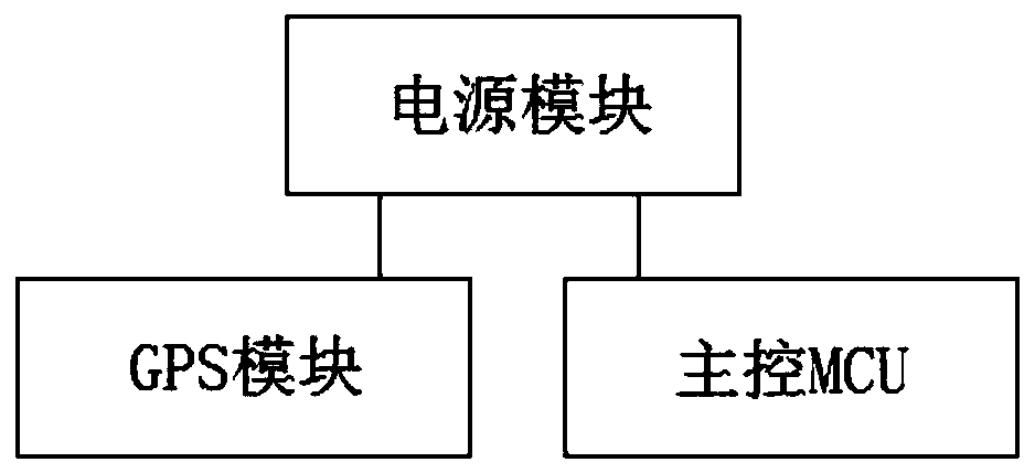
[0022] Such as figure 1 As shown, a GPS synchronization controller includes a main control MCU, a GPS module, and a power module. The power module includes a power input circuit, a power conversion circuit, and a power output circuit. The power input circuit is connected to the power conversion circuit. The circuits are respectively connected to the main control MCU and GPS module, the GPS module is connected to the main control MCU, and the main control MCU is connected to the power output circuit. The power conversion circuit is used to convert the power supply voltage of the power input circuit into the working voltage of the main control MCU and GPS module. .

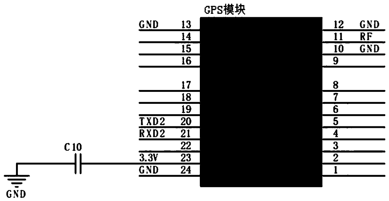
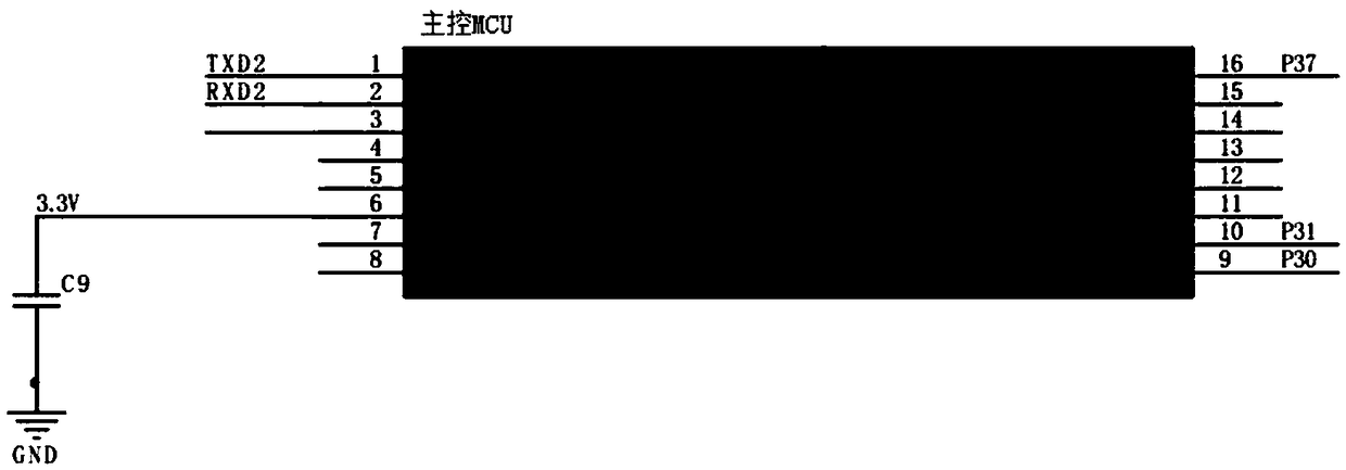
[0023] Among them, such as figure 2 with image 3 As shown, the GPS module selects the GPS-ADGM 332D chip, the main control MCU selects the STC8F2K08S2-16Pin chip, the input p...


PUM


Abstract

The invention discloses a GPS synchronization controller. The GPS synchronization controller comprises a main control unit (MCU), a GPS module and a power module, wherein the power module comprises apower input circuit, a power conversion circuit and a power output circuit; and the power input circuit is connected with the power conversion circuit, the power conversion circuit is connected with the main control unit (MCU) and the GPS module, the GPS module is connected with the main control unit (MCU), the main control unit (MCU) is connected with the power output circuit, and the power conversion circuit is used for converting the power voltage of the power input circuit into the working voltage of the main control unit (MCU) and the GPS module. The GPS module is arranged in the GPS synchronization controller, a GPS time signal sent by a GPS satellite is received through an antenna and transmitted to the main control unit (MCU), the main control unit (MCU) reads the time, makes a corresponding judgment in real time and sends a corresponding instruction to an external RGB lamp, and then a remote RGB lamp light synchronization function is achieved.

Description

Technical field [0001] The invention relates to the technical field of lighting control, in particular to a GPS synchronization controller. Background technique [0002] Because LED diodes have the characteristics of low power consumption, long service life, and good light intensity stability of the light source, LED lighting and lighting products and very common applications in various use environments also have different needs and developments in the application process. space. For example, in an LED lamp or lighting product, the mode of different light changes can be adjusted, and the mode of synchronous light change control of the LED lamp or lighting product can be realized in the environment between different distances. [0003] The existing LED lighting mode is relatively single, one is that the solid color lamp cannot change the color and has no control function; the other is that the lamp is externally connected to a single controller, and the user provides manual single ...

Claims


Application Information

Patent Timeline
IPC IPC(8): H05B33/08H05B37/02H05B44/00
CPCH05B45/00H05B47/16Y02B20/40
Inventor 陈根海
Owner JIANGSU FEITIAN LIGHTING CO LTD
Learn More