Push head unit of pump dispenser

A head unit and pump-type technology, applied in the field of head unit, can solve the problems of inconvenient use, and achieve the effects of maintaining cleanliness, cleaning or replacement, and cleaning and replacement operations.

Active Publication Date: 2015-11-04
APOLLO IND
View PDF6 Cites 5 Cited by
  • Summary
  • Abstract
  • Description
  • Claims
  • Application Information

AI Technical Summary

Problems solved by technology

[0005] However, in the pressing head disclosed in the Korean Patent No. 10-1127411, if the brush head part 40 made of rubber material is to be separated and cleaned, it is necessary to hold and pull the handle protrusion 45 to separate it from the brush head. The head mounting part 20, and after cleaning, it is necessary to elastically deform and insert the hook engaging part 43, which causes inconvenience in use

Method used


Image

  • Push head unit of pump dispenser
  • Push head unit of pump dispenser
  • Push head unit of pump dispenser

Examples


Embodiment Construction

[0043] Below, refer to the attached figure 2 to attach Figure 14 Preferred embodiments according to the present invention will be described in detail.

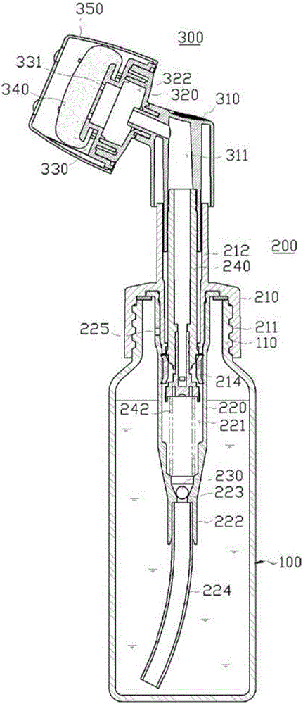
[0044] The pump dispenser applying the present invention is installed in a container (BOTTLE) carrying fluid or gel-like cosmetics (hereinafter referred to as content), etc., and is used to suck and spray the content to the massager. Press the head side of the head, so that you can directly apply to the skin or perform massage or cleansing (Clensing) functions through the massage part without hands.

[0045]

[0046] refer to figure 2 , the pump dispenser 200 of the present invention is used to suck and spray the contents of the container 100 to the side of the head unit 300 through the repeated pressing operation of the head unit 300, and includes: a cover 210 installed on the container 100 The inlet (110; neck); the cylinder 220 is coaxially arranged on the inner side of the cover 210, and the lower part has a suctio...


PUM


Abstract

The present invention relates to a push head unit of a pump dispenser. The aim of the present invention is to be able to apply dispensed contents through a massage member directly onto the skin without using the palm of the hand, and to make attachment/detachment of the massage member easier during cleaning or replacing of same. To this end, the "push head unit of a pump dispenser" according to the present invention comprises: a head-body (310) coupled to the upper end of a piston shaft (240), and having a content discharge flow passage (311) formed on the inside thereof; a nozzle base (320) of which the centre on the rear surface has a coupling opening (321) coupled by insertion into the fore-end part of the discharge flow passage (311) of said head-body (310) while also linking through to same, and of which the front surface is provided with a first cylinder wall (323) forming a content-discharging space (322) while having a coupling protrusion (324) in the form of a belt on the outer circumferential surface thereof, and is provided with a second cylinder wall (326) constituted so as to form a gap in conjunction with said first cylinder wall while surround same and having a wave-shaped first concavo-convex hollow (325) on the outer circumferential surface thereof; a nozzle cover (330) in which a plurality of nozzle holes (331) are perforated in central positions in order to allow outward discharge of the contents that have been discharged from the content-discharging space (322) of said nozzle base (320), and which is detachably coupled while covering the front surface of said nozzle base (320), and of which the rear surface is provided with a first coupling wall (333) coupled so as to surround the outer perimeter of the first cylinder wall (323) of said nozzle base (320) and having on the inner circumferential surface thereof a coupling hollow (332) in the form of a belt that mates in concavo-convex fashion with said coupling protrusion (324), and is provided with a second coupling wall (335) coupled so as to surround the outer perimeter of the second cylinder wall (326) of said nozzle base (320) and having on the inner circumferential surface thereof a wave-shaped second concavo-convex hollow (334) adapted to mate with said first concavo-convex hollow (325); a massage member (340) (340A) which is disposed on a front part of said nozzle cover (330) and is configured to touch skin elastically while applying the contents that have been discharged through said nozzle holes (331); and an over cap (350) which is constituted in the shape of a cup so as to detachably cover the second coupling wall (335) of said nozzle cover (330) while wrappping around said massage member(340) (340A), and in which a latching shoulder (351) is constituted so as to project along the inner circumferential surface of the opening; and, in the present invention, a locking protrusion (337) is formed to the rear of the second coupling wall (335) of said nozzle cover (330) so as to latch onto the inside of said latching shoulder (351) of said over cap (350), and a pair of locking knobs (338L) (338R) are disposed at opposing positions thereon so as to be able to selectively undo the state of latching of said locking protrusion (337) when pressed toward the center part.

Description

technical field [0001] The present invention relates to a pump-type dispenser press head unit, in particular to a device that can evenly spread the content sprayed by the press-head unit onto the skin with the suction operation of the pump-type dispenser without hands Or wash (massage) "pump dispenser head unit". Background technique [0002] Generally, the pump dispenser is installed in a container carrying liquid or pasty cosmetics or other contents, and discharges the contents in units of a predetermined amount by pressing the head, and is applied to cosmetics, detergents, washing Hair water, food and other product groups. [0003] This existing pump type distributor is roughly divided into the following constituent elements: a pump unit, which is combined with the inlet of the container, and is formed with a pressure chamber to suck the content and temporarily store it; The pressure chamber applies pressure to expel the contents to an external nozzle. By repeatedly pr...

Claims


Application Information

Patent Timeline
Patent Type & Authority Applications(China)
IPC IPC(8): B65D47/42B65D47/34A45D34/04B05B11/00
CPCA45D34/042A46B5/0095A46B11/002A46B2200/102A46B2200/1046B05B11/3001B05B11/1001B65D47/42B65D47/00A45D34/04B05B11/00
Inventor 李镕大
Owner APOLLO IND
Why Eureka
Try Eureka