Conveyer belt type dispensing mechanism

A technology of dispensing mechanism and conveyor belt, which is applied in the direction of coating, liquid coating device on the surface, etc., can solve the problems of low efficiency and limited effect, and achieve the effect of high efficiency and fast speed

Active Publication Date: 2015-11-11
南通江海港建设工程有限公司
View PDF6 Cites 10 Cited by
  • Summary
  • Abstract
  • Description
  • Claims
  • Application Information

AI Technical Summary

Problems solved by technology

[0003] However, the existing automatic dispensing machines generally use a turntable type or manually place the circuit board to be processed on the platform, and dispensing is performed by moving the dispensing head of the mobile dispensing device, which requires manual feeding. And artificial fixation, the effect is limited, and the efficiency is not high

Method used


Image

  • Conveyer belt type dispensing mechanism
  • Conveyer belt type dispensing mechanism
  • Conveyer belt type dispensing mechanism

Examples


Embodiment Construction

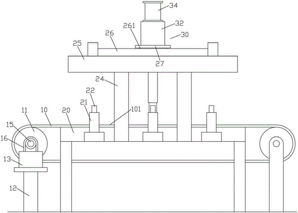
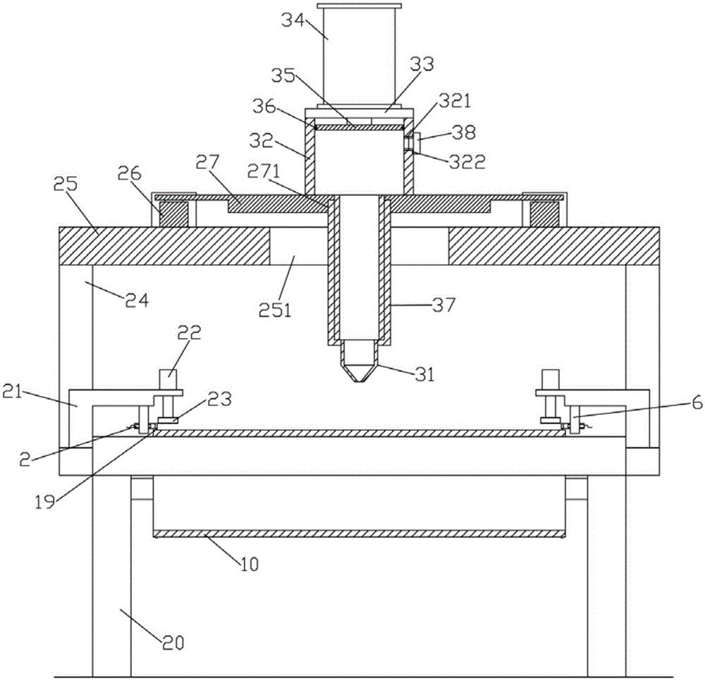
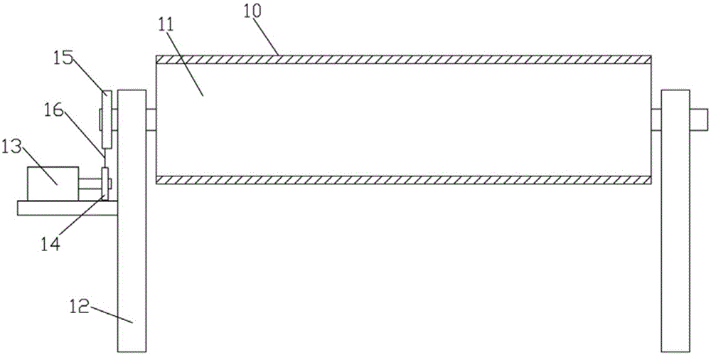
[0016] Examples, see e.g. Figures 1 to 4 As shown, a conveyor belt type dispensing mechanism includes a conveyor belt 10 and a frame 20, the conveyor belt 10 is tensioned on two drive rollers 11, and the two ends of the drive roller 11 are hinged on two vertical legs 12, the vertical legs 12 are fixed on the bottom surface, one of the vertical legs 12 is fixed with a drive motor 13, the output shaft of the drive motor 13 is fixed with a drive wheel 14, and the fixed vertical legs 12 of the drive motor 13 One end of the transmission roller 11 is fixed with a transmission wheel 15, the belt 16 is tensioned on the transmission wheel 15 and the driving wheel 14, the frame 20 is fixed on the ground, the top plate of the frame 20 extends into the conveyor belt 10, and is in the conveying The back side of the conveying part 101 of the top of belt 10, the both sides of the top plate of frame 20 are fixed with a plurality of pressing cylinder fixed mounts 21, and the top of pressing c...


PUM


Abstract

The invention discloses a conveyer belt type dispensing mechanism which comprises a conveyer belt and a rack. The conveyer belt is tensioned on two driving rolls. A top plate of the rack stretches into the conveyer belt and is located on the back face of a conveying portion on the upper portion of the conveyer belt. A plurality of compressing air cylinder fixing frames are fixed to the two sides of the top plate of the rack. The upper portions of the compressing air cylinder fixing frames are located above the side of the conveyer belt and fixedly provided with compressing air cylinders. Push rods of the compressing air cylinders are vertically downwards and are fixedly provided with elastic clamping blocks. An upper supporting frame is fixed to the top plate of the rack. An upper supporting plate of the upper supporting frame is located above the conveyer belt. Rodless air cylinders are fixed to the two sides of the upper supporting plate. A connecting plate is fixed to sliding blocks on the two rodless air cylinders and fixedly provided with a dispensing device. A circuit board is conveyed through the conveyer belt, and dispensing is carried out on the circuit board in the conveying process. The conveyer belt type dispensing mechanism is high in efficiency and high in speed, and manual feeding is not needed.

Description

Technical field: [0001] The invention relates to the technical field of glue dispensing equipment, and more specifically relates to a conveyor belt type glue dispensing mechanism. Background technique: [0002] There are more and more dispensing processes in industrial production, and the requirements are becoming more and more stringent. Traditional dispensing is manually operated by workers. With the rapid development of automation technology, manual dispensing is far from meeting the needs of the industry and is gradually being replaced by automatic dispensing machines. Automatic dispensing machines are widely used in industrial production, such as integrated circuits, printed circuit boards, electronic components, auto parts, handbags, packaging boxes, etc. The application of automatic dispensing machine has greatly improved production efficiency, improved product quality, and can realize some processes that cannot be completed by manual dispensing. [0003] However, t...

Claims


Application Information

Patent Timeline
Patent Type & Authority Applications(China)
IPC IPC(8): B05C5/02B05C11/10
Inventor 任新根
Owner 南通江海港建设工程有限公司
Why Eureka
Try Eureka