Lock catch plate punching die

A locking plate and punching technology, which is applied in the field of punching dies, can solve the problems of easy material jams during stripping, easy damage of lower dies, and reduced production efficiency, so as to save operating time, reduce workpiece burrs, The effect of improving productivity

Active Publication Date: 2015-11-11
SHANDONG AOLIN CAR FITTINGS
View PDF6 Cites 1 Cited by
  • Summary
  • Abstract
  • Description
  • Claims
  • Application Information

AI Technical Summary

Problems solved by technology

The lower die block under the B-type punch of the patented locking plate punching die is easily damaged, and the material jam phenomenon is prone to occur when the material is removed, which seriously reduces the production efficiency

Method used


Image

  • Lock catch plate punching die
  • Lock catch plate punching die
  • Lock catch plate punching die

Examples


Embodiment 1

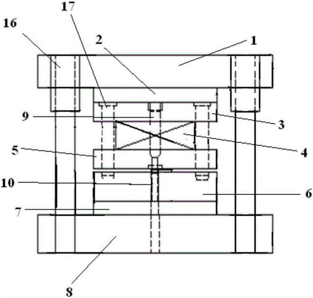
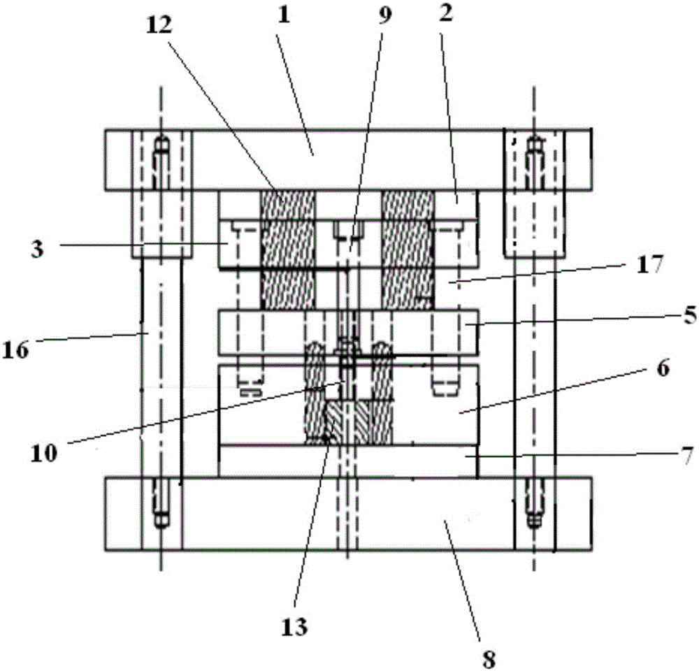
[0025] A punching die for a locking plate, the structure of which is as follows image 3 and Figure 4 As shown, it includes an upper mold assembly and a lower mold assembly. The upper mold assembly includes an upper mold base 1, an upper backing plate 2 and an upper fixing plate 3, and the upper backing plate 2 and the upper fixing plate 3 are sequentially arranged on the Below the upper mold base 1, a punch 9 is arranged on the upper fixing plate 3, and a tungsten-containing high-speed tool steel die edge of the type SKH51 is set on the punch 9, and screw structures 17 are arranged downwards at both ends of the upper fixing plate 3. The screw structure 17 runs through both ends of the stripper plate 5 and connects the lower die assembly. The stripper plate 5 is provided with 9 punch holes for the punch 9 to move up and down, and the stripper plate 5 is connected to the upper die base 1. A nitrogen spring 12 is provided, and the lower mold assembly includes a lower mold base...


PUM


Abstract

The invention relates to a lock catch plate punching die. The lock catch plate punching die comprises an upper die assembly and a lower die assembly which are connected to each other. The upper die assembly is provided with a punch (9), and the punch (9) is provided with a die cutter opening. A lower die inlet block (10) for assisting punching is arranged at the position, corresponding to the punch (9), in the lower die assembly. A workpiece (11) to be punched is fixedly arranged on the lower die assembly. A stripping plate (5) is arranged below the upper die assembly. Nitrogen springs (12) for assisting stripping are arranged between the stripping plate (5) and the upper die assembly. A lower die cushion block (13) connected with the lower die inlet block (10) is arranged below the lower die inlet block (10). Compared with the prior art, the lock catch plate punching die has the beneficial effects of being high in production efficiency, good in product quality, low in maintenance cost and the like.

Description

technical field [0001] The invention relates to a punching die, in particular to a punching die for a locking plate. Background technique [0002] The company's existing D-117 lock plate punching die, its structure is as follows figure 1 and figure 2 As shown, it includes an upper mold assembly and a lower mold assembly, wherein the upper mold assembly includes an upper mold base 1, an upper backing plate 2 and an upper fixing plate 3, and the upper backing plate 2 and the upper fixing plate 3 are sequentially arranged from top to bottom It is arranged below the upper mold base 1, and the upper fixing plate 3 is provided with a downward punch 9, the punch 9 is provided with a die edge, the material of the die edge is CR12MOV, and the lower mold assembly includes the lower die base 8, and from The lower formwork 6 and the lower backing plate 7 are arranged on the lower mold base 8 in turn from top to bottom. The lower formwork 6 is provided with a lower mold entry block 10...

Claims


Application Information

Patent Timeline
Patent Type & Authority Applications(China)
IPC IPC(8): B21D28/34B21D43/00B21D45/08
Inventor 曹萍清
Owner SHANDONG AOLIN CAR FITTINGS
Why Eureka
Try Eureka