
Drilling machine used for ladder string of composite material cable bridge stand and capable of machining out six holes simultaneously

A cable tray, composite material technology, applied in boring/drilling, metal processing equipment, drilling/drilling equipment, etc., can solve the problems of time delay, low work efficiency, unsuccessful installation, etc., to avoid drilling The hole position is not uniform, saving time and improving work efficiency

Active Publication Date: 2015-11-11
HEBEI YANWU EXPLODEPROOF ELECTRICAL EQUIP
View PDF6 Cites 1 Cited by
  • Summary
  • Abstract
  • Description
  • Claims
  • Application Information

AI Technical Summary

Problems solved by technology

[0002] The bridge frame is composed of ladder sides. Before the combination, the ladder sides need to be drilled, and then assembled with bolts. The drilling before the combination work of the prior art is measured by a ruler, and then drawn with an electric drill. Drilling is prone to deviation and drilling position offset, resulting in unsuccessful final installation, time-consuming, time-consuming and labor-intensive, and low work efficiency

Method used


Image

  • Drilling machine used for ladder string of composite material cable bridge stand and capable of machining out six holes simultaneously
  • Drilling machine used for ladder string of composite material cable bridge stand and capable of machining out six holes simultaneously
  • Drilling machine used for ladder string of composite material cable bridge stand and capable of machining out six holes simultaneously

Examples


Embodiment Construction

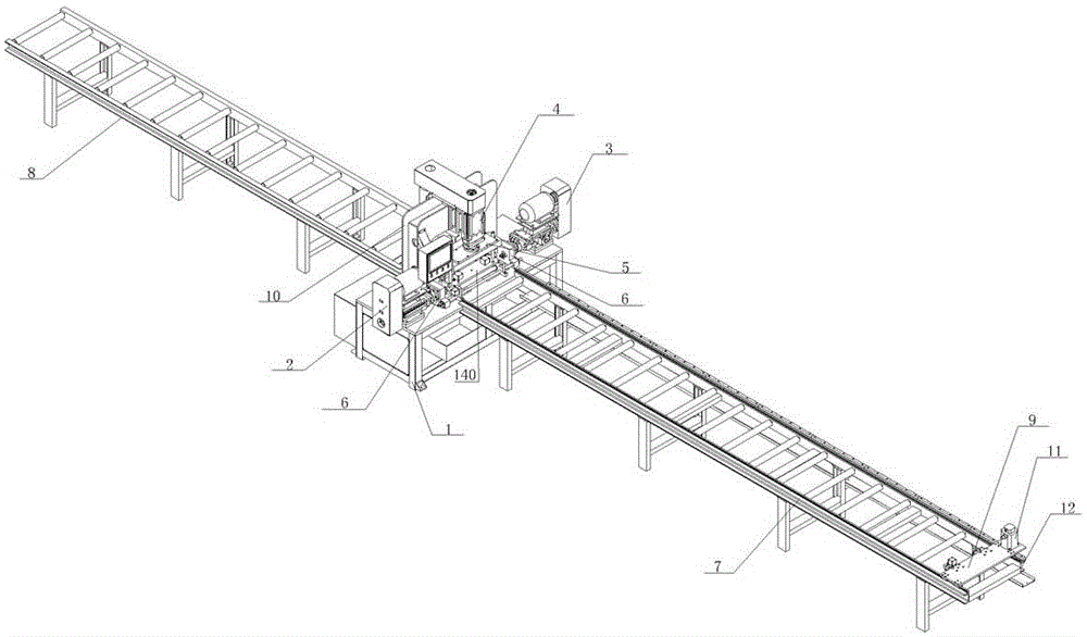
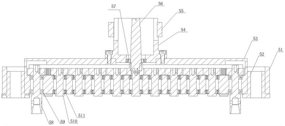
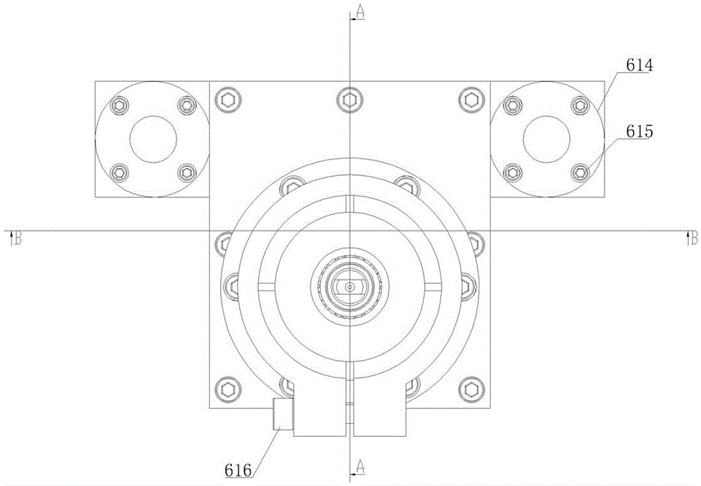
[0013] The present invention will be described in detail below with reference to the accompanying drawings. As shown in the drawings, the structure of the present invention includes a base 1, a left drilling power head 2, a right drilling power head 3, an upper drilling power head 4, a feeding bed 7, a feeding bed 8, and a servo trolley 9. Return frame 10, servo trolley power unit 11, servo chain groove 12, chain 13, limit device consisting of main cylinder 141, pressure plate 142, pressure rod 143, secondary cylinder 144, side cylinder 145, and side pressure rod 146 140, consisting of the upper multi-axis device box 51, the upper linear bearing 52, the upper multi-axis device upper cover 53, the upper connecting sleeve 54, the upper tightening ring 55, the upper driving shaft 56, the upper deep groove ball bearing A57, and the upper output shaft 58. The upper drilling power head multi-axis device 5 composed of the upper contact bearing 59, the upper intermediate shaft 510, an...


PUM


Abstract

The invention relates to a drilling machine used for a ladder string of a composite material cable bridge stand and capable of machining out six holes simultaneously. The drilling machine is characterized in that an upper drilling power head is installed on a bracket shaped like a Chinese character 'hui', a left side drilling power head and a right side drilling power head are arranged at the two sides of the upper drilling power head respectively, an upper drilling power head multiaxial device is arranged below the upper drilling power head, side direction drilling power head multiaxial devices are arranged at the inner side of the left side drilling power head and the inner side of the right side drilling power head respectively, a feeding bed is arranged in front of a base, a blanking bed is arranged behind the base, and a servo cart is arranged at the top end of the feeding bed. The drilling machine has the advantages that the six holes can be drilled continuously and simultaneously, time and labor are saved, defects that drilling holes are inconsistent in position, and the installation is inconvenient are avoided, no measurement is required, time of workers is saved, the working efficiency is raised, and the automated drilling is achieved through the PLC control.

Description

technical field [0001] The invention relates to the composite bridge industry, in particular to a drilling machine for simultaneously processing six holes on the ladder side of a composite material cable bridge. Background technique [0002] The bridge frame is composed of ladder sides. Before the combination, the ladder sides need to be drilled, and then assembled with bolts. The drilling before the combination work of the prior art is measured by a ruler, and then drawn with an electric drill. Drilling is prone to deviation and drilling position offset, resulting in unsuccessful final installation, time-consuming, time-consuming and labor-intensive, and low work efficiency. Contents of the invention [0003] The technical problem to be solved by the present invention is to overcome the deficiencies of the prior art, and provide a drilling machine for processing six holes while the ladder side of the composite cable tray is used. The technical solution adopted by the pres...

Claims


Application Information

Patent Timeline
Patent Type & Authority Applications(China)
IPC IPC(8): B23B39/16B23B41/00B23B47/00
CPCB23B39/16B23B41/00B23B47/00
Inventor 吕文勇
Owner HEBEI YANWU EXPLODEPROOF ELECTRICAL EQUIP
Learn More