
Packaging method for while-drilling acoustic wave transducer

A technology of acoustic wave transducer and encapsulation method, which is applied in the direction of coating, etc., can solve the problems of easy retention of air bubbles, destruction of transducer insulation, destruction, etc., and achieve the effect of uniform pressure and increased sealing effect

Active Publication Date: 2015-11-11
CHINA NAT OFFSHORE OIL CORP +1
View PDF7 Cites 2 Cited by
  • Summary
  • Abstract
  • Description
  • Claims
  • Application Information

AI Technical Summary

Problems solved by technology

Because there is a mud hole in the middle of the drilling tool, the acoustic transducer is installed on the outer wall of the drill collar, and it is difficult to be immersed in oil to seal it like the cable acoustic logging tool. Therefore, the acoustic transducer while drilling is generally packaged separately. The appearance of the acoustic wave transducer while drilling in the prior art is sealed by high-temperature epoxy resin, and the high-temperature wires are led out. The disadvantage of the acoustic wave transducer while drilling is that the epoxy resin sealing layer is easy to retain air bubbles, which leads to transduction under high temperature and high pressure conditions. The insulation of the transducer is reduced or damaged, and the PTFE sheath of the high-temperature wire cannot be well bonded to the epoxy resin. Under high temperature and high pressure, the mud may enter the transducer along the wire sheath and damage the insulation of the transducer.

Method used


Image

  • Packaging method for while-drilling acoustic wave transducer
  • Packaging method for while-drilling acoustic wave transducer
  • Packaging method for while-drilling acoustic wave transducer

Examples


Embodiment Construction

[0023] In order to make the purpose, technical solution and advantages of the present invention more clear, the embodiments of the present invention will be described in detail below in conjunction with the accompanying drawings. It should be noted that, in the case of no conflict, the embodiments in the present application and the features in the embodiments can be combined arbitrarily with each other.

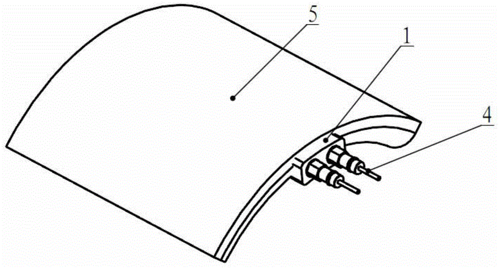
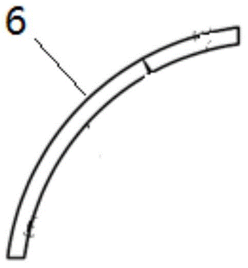
[0024] Such as figure 1 and figure 2 As shown, an acoustic wave transducer while drilling includes a casing 1 and a rubber layer 5 covering it, as well as a piezoelectric ceramic crystal 2 and an electrical connector 4 encapsulated in the casing 1. The acoustic wave transducer while drilling The packaging method of the device includes the following steps: 1) connecting the electrodes of the piezoelectric ceramic crystal 2 to the electrical connector 4 through the lead wire 3, and placing them in a mold; 2) preparing a packaging material, the packaging material and the piezo...


PUM


Abstract

Provided is a packaging method for a while-drilling acoustic wave transducer. The while-drilling acoustic wave transducer comprises a rubber layer, an outer shell, a piezoelectric ceramic crystal and an electric connector, wherein the piezoelectric ceramic crystal and the electric connector are packaged in the outer shell. The packaging method comprises the following steps that (1), an electrode of the piezoelectric ceramic crystal and the electric connector are connected with each other through a lead and placed in a mold; (2), packaging materials are prepared, and the packaging materials are identical with the piezoelectric ceramic crystal in thermal expansion coefficient; (3), the mold is filled with the packaging materials which are heated to the melting point, the outer shell is formed after the packaging materials are cooled and solidified, and the packaging materials, the piezoelectric ceramic crystal and the electric connector are made to be packaged into a whole; and (4), the rubber layer is laid on the outer side of the outer shell. By means of the packaging method, it is guaranteed that the piezoelectric ceramic crystal in the transducer cannot be damaged in the packaging process, the rubber layer is laid on the outer side of the outer shell of the while-drilling acoustic wave transducer so as to resist vibration, and installation of the transducer is facilitated.

Description

technical field [0001] The invention relates to a packaging method of an acoustic wave transducer while drilling. Background technique [0002] The acoustic wave transducer while drilling is the most important component of the acoustic logging tool while drilling. When the instrument is working, the acoustic wave is generated by the transmitting transducer built in the instrument, and then received by the receiving transducer in the same instrument. Acoustic information such as wave velocity and attenuation of each mode wave is used to evaluate the properties of the borehole wall medium. Because there is a mud hole in the middle of the drilling tool, the acoustic transducer is installed on the outer wall of the drill collar, and it is difficult to be immersed in oil to seal it like the cable acoustic logging tool. Therefore, the acoustic transducer while drilling is generally packaged separately. The appearance of the acoustic wave transducer while drilling in the prior art...

Claims


Application Information

Patent Timeline
Patent Type & Authority Applications(China)
IPC IPC(8): B29C45/14
CPCB29C45/14
Inventor 李辉罗瑜林陈洪海刘西恩
Owner CHINA NAT OFFSHORE OIL CORP
Learn More