Automobile engine oil-gas separator

A technology of oil and gas separator and automobile engine, which is applied in the direction of engine components, machines/engines, mechanical equipment, etc. It can solve the problems of poor filtering effect and low efficiency, and achieve the effect of protecting the environment, high efficiency and good filtering effect

Active Publication Date: 2015-11-11
宁海县雄达模塑有限公司
View PDF7 Cites 7 Cited by
  • Summary
  • Abstract
  • Description
  • Claims
  • Application Information

AI Technical Summary

Problems solved by technology

[0002] The oil-air separator is connected next to the crankcase ventilation valve of the engine, because when the engine is working, the blow-by gas of the cylinder and the oil vapor will generate pressure, which will cause damage to the engine, so it needs to be vacuumed through the crankcase ventilation valve, because There is a large amount of oil vapor in the gas extracted by the crankcase ventilation valve, so the oil-gas separator mainly separat...

Method used


Image

  • Automobile engine oil-gas separator
  • Automobile engine oil-gas separator
  • Automobile engine oil-gas separator

Examples


Embodiment Construction

[0019] The present invention will be further described below in conjunction with the accompanying drawings and specific embodiments.

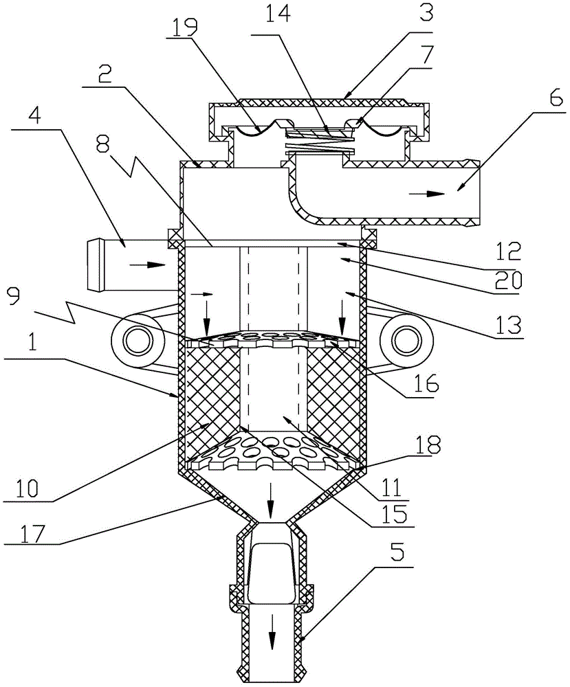
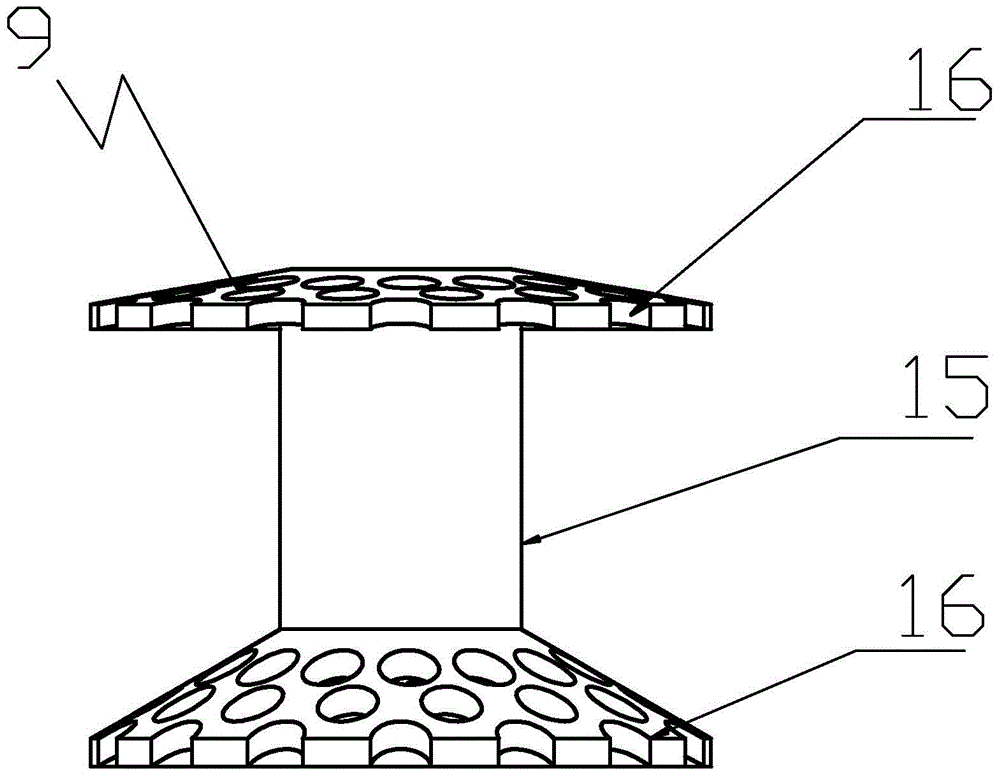
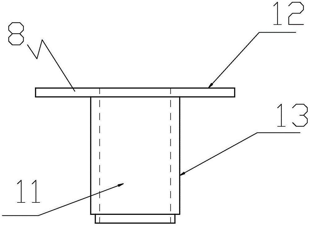
[0020] As shown in the figure, the present invention provides an automobile engine oil-air separator, which includes a lower hollow body 1 and an upper casing 2, and the side of the lower hollow body 1 is connected with an air intake pipe 4 for entering mixed oil and gas, The bottom of the lower cavity 1 is provided with an oil outlet pipe 5, the upper casing 2 is provided with an air outlet pipe 6, and the lower cavity 1 is provided with a first separation mechanism and a second separation mechanism, The first separation mechanism includes a separation bracket 8 for guiding and a cavity 20 communicating with the intake pipe 4, the cavity 20 is located at the upper part of the lower cavity 1, and the upper end of the separation bracket 8 is sealed and fixed on the On the inner wall of the upper part of the cavity 20, the air inlet pipe 4 is tan...


PUM


Abstract

The invention discloses an automobile engine oil-gas separator. The automobile engine oil-gas separator comprises a lower hollow cavity (1) and an upper shell (2); a gas inlet pipe (4) where mixed oil and gas enters is connected to the lateral face of the lower hollow cavity (1); an oil outlet pipe (5) is arranged at the bottom of the lower hollow cavity (1); a gas outlet pipe (6) is arranged on the upper shell (2); the lower hollow cavity (1) is internally provided with a first separation mechanism and a second separation mechanism; the first separation mechanism comprises a separation support (8) used for guidance and a cavity body (20) communicated with the gas inlet pipe (4); the cavity body (20) is located in the upper portion of the lower hollow cavity (1); the upper end of the separation support (8) is fixed to the inner wall of the upper portion of the cavity body (20) in a sealed mode; the gas inlet pipe (4) and the outer circumference of the cavity (20) is in tangential connection. The automobile engine oil-gas separator is high in efficiency and good in filtering effect.

Description

technical field [0001] The invention relates to an oil-gas separator, in particular to an automobile engine oil-gas separator. Background technique [0002] The oil-air separator is connected next to the crankcase ventilation valve of the engine, because when the engine is working, the blow-by gas of the cylinder and the oil vapor will generate pressure, which will cause damage to the engine, so it needs to be vacuumed through the crankcase ventilation valve, because There is a large amount of oil vapor in the gas extracted by the crankcase ventilation valve, so the oil-gas separator mainly separates the oil vapor into oil and steam, so that the oil is collected by the pan and flows back to the engine for reuse, and the steam flows to the engine for re-combustion. To prevent direct entry into the atmosphere and cause air pollution, according to the prior art, an oil-gas separator for automobile diesel engines has been disclosed on the website of the State Intellectual Proper...

Claims


Application Information

Patent Timeline
IPC IPC(8): F01M13/04
Inventor 葛诗健
Owner 宁海县雄达模塑有限公司
Why Eureka
Try Eureka