
A waterway control valve structure

A waterway control valve, valve core technology, applied in valve details, diaphragm valves, valve devices, etc., can solve problems such as poor applicability, inappropriate solenoid valves, and valve diaphragms are easily damaged, and achieve reasonable structural design and avoid water hammer. Vibration, long life effect

Active Publication Date: 2017-06-27
QUANZHOU ZONGNENG ELECTROMAGNETIC VALVE CO LTD
View PDF1 Cites 0 Cited by
  • Summary
  • Abstract
  • Description
  • Claims
  • Application Information

AI Technical Summary

Problems solved by technology

[0003] But in this invention application, there is following defect in the setting of valve mold: (1) although its water outlet is provided with some ribs and protects valve diaphragm, can not provide enough protection, and valve diaphragm has been extruded water inlet and outlet risk, and it will collide with the water outlet, which is easy to be damaged; (2) the invention application cannot completely eliminate the occurrence of water hammer, although there will be no water hammer between the valve diaphragm and the water inlet, but the valve diaphragm and the water outlet (3) The applicability of this invention application is poor. When the gap between the ribs is too large, the valve diaphragm is easily damaged. When the gap between the ribs is too small, the water flow will be very small, so it is only applicable Suitable for solenoid valves with low water pressure and small flow, not suitable for solenoid valves with high water pressure or large flow requirements

Method used


Image

  • A waterway control valve structure
  • A waterway control valve structure
  • A waterway control valve structure

Examples


Embodiment Construction

[0035] In order to further explain the technical solution of the present invention, the present invention will be described in detail below through specific examples.

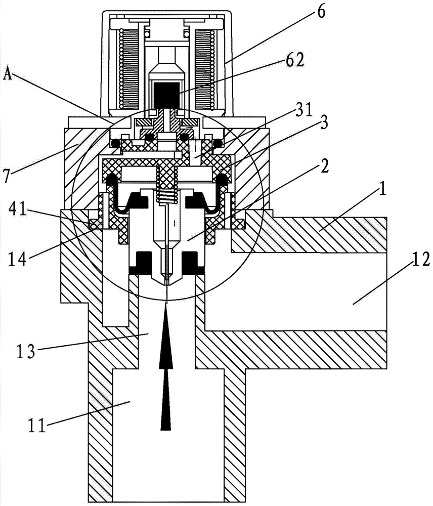
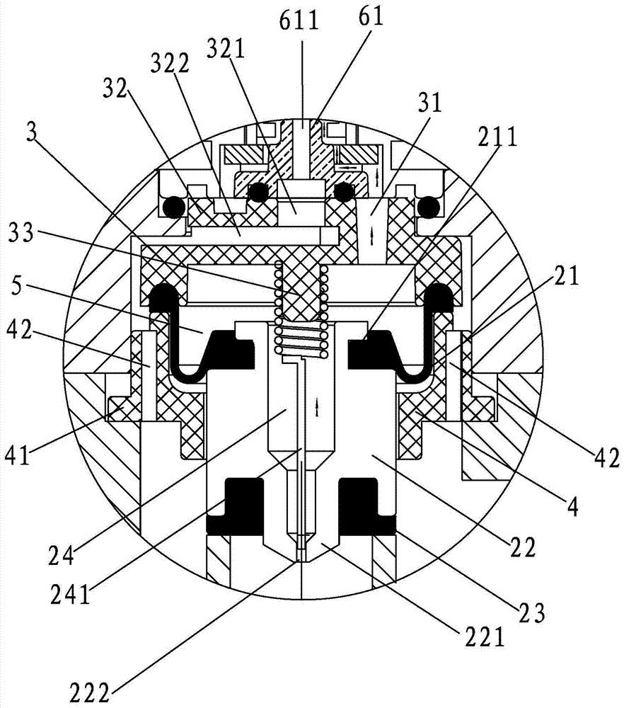
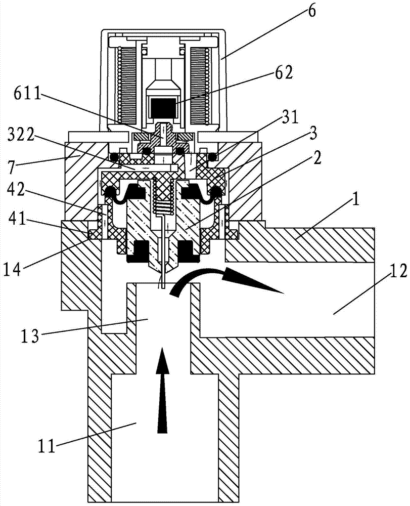
[0036] A waterway control valve structure, such as Figure 1-Figure 2 As shown, it includes a valve body 1 with a water inlet 11 and a water outlet 12, a valve core set 2 installed in the valve body 1, a diaphragm gland 3 and a shaft sleeve 4, and a water inlet 11 and a water outlet 12 are formed. There is a through hole 13 , the diaphragm gland 3 is installed above the spool set 2 , and the spool set 2 is arranged above the through hole 13 .

[0037] The spool kit 2 is composed of a rubber diaphragm 21, a spool body 22 and a water-stop rubber pad 23 from top to bottom. The spool body 22 is provided with a water inlet channel 24, and the lower part of the spool body 22 has a convex post 221. A balance hole 222 is defined at the lower end of the boss 221 , one end of the balance hole 222 communicates with the w...


PUM


Abstract

The invention discloses a waterway control valve structure. The waterway control valve structure comprises a valve body with a water inlet and a water outlet, a valve element sleeve piece installed in the valve body, a membrane gland and a shaft sleeve. A passing hole is formed between the water inlet and the water outlet, the membrane gland is installed on the upper portion of the valve element sleeve piece, and the valve element sleeve piece is arranged on the upper portion of the passing hole and is composed of a rubber membrane, a valve element body and a water stop rubber gasket from top to bottom. A water inlet hole channel is formed in the valve element body and communicated with the water inlet. The water stop rubber gasket is arranged at the lower end of the valve element body in a clamping mode, the water stop rubber gasket is in sealing contact with the upper end face of the passing hole, the rubber membrane is arranged at the upper end of the valve element body in a clamping mode, the rubber membrane and the lower surface of the membrane gland are connected together in a sealing mode, and a water pressure balance cavity is formed between the rubber membrane and the membrane gland. The waterway control valve structure is reasonable in structural design, water hammer vibration can be avoided, the pressure endurance capability is high, and the service life of the waterway control valve structure is long.

Description

technical field [0001] The invention relates to a waterway control valve structure. Background technique [0002] Most of the existing domestic water products are controlled by non-contact automatic control valves, which are prone to water hammer vibration when the product is closed. When some users use water in the dead of night, the noise of water hammer vibration has reached the level of disturbing residents. Chinese invention patent application for a solenoid valve seat and waterway structure without water hammer vibration sound (patent application number is 201210438334.8), which is composed of solenoid valve, solenoid valve seat, valve seat cylinder, valve module, and water inlet booster ring connection , change the structure of the solenoid valve valve module to close the water outlet to the structure of the solenoid valve valve module to close the water inlet hole, due to the promotion of the water inlet pressure of the water inlet hole, the speed of the valve modul...

Claims


Application Information

Patent Timeline
Patent Type & Authority Patents(China)
IPC IPC(8): F16K7/12F16K31/06
CPCF16K7/12F16K31/0675
Inventor 鲍伟军
Owner QUANZHOU ZONGNENG ELECTROMAGNETIC VALVE CO LTD
Learn More