
Pressure sensor used in air conditioner

A technology of pressure sensor and air conditioner, applied in the direction of measuring fluid pressure, instruments, measuring devices, etc., can solve the problems of weak anti-electromagnetic interference ability, difficult to ensure re-sealing, unreliability, etc., and achieve strong anti-electromagnetic interference ability and good electromagnetic protection , the effect of simple assembly

Inactive Publication Date: 2015-11-11
NINGBO CRRC TIMES TRANSDUCER TECH CO LTD
View PDF7 Cites 4 Cited by
  • Summary
  • Abstract
  • Description
  • Claims
  • Application Information

AI Technical Summary

Problems solved by technology

[0004] 1) The ability to resist electromagnetic interference is weak, and there is no separate shielding space for the signal processing circuit
[0005] 2) The withstand voltage design is weak, and the intermediate insulating layer is made of paper material, so the reliability is obviously insufficient
[0006] 3) The reliability of the sealing interface is low, and the taper of the sealing interface and the taper of the joint on the pipeline are prone to deviations, and it is difficult to ensure re-sealing after disassembly and assembly once
[0007] 4) The pressure core needs two seals, which affects the reliability of the medium seal
[0008] 5) External glue sealing, the process is complicated and unreliable, and it is prone to sealing failure in harsh environments

Method used


Image

  • Pressure sensor used in air conditioner
  • Pressure sensor used in air conditioner
  • Pressure sensor used in air conditioner

Examples


Embodiment Construction

[0024] The present invention will be further described below in conjunction with the embodiments of the accompanying drawings.

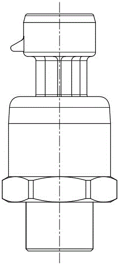
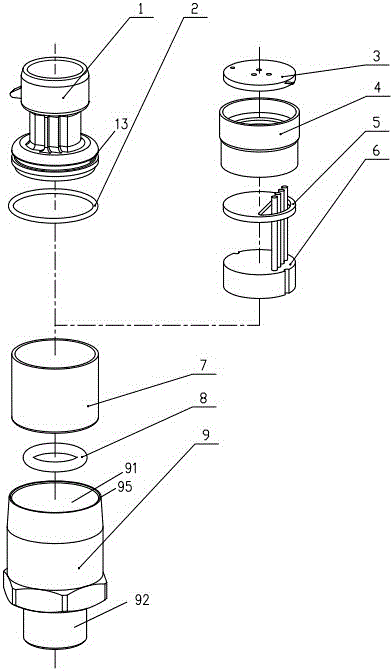
[0025] Such as figure 2 , 3 , 4, pressure sensor for air conditioner, including three-core packard connector 1, connector sealing ring 2, circuit board assembly 3, shielding shell 4, partition 5, pressure core 6, insulating sleeve 7, core sealing ring 8. Shell 9.

[0026] The shell 9 is divided into upper and lower parts, the upper part is a cavity 91 for accommodating the insulating sleeve 7 and the three-core packard connector 1, the lower part is provided with a connector 92 for connecting the place of use, and the upper part and the lower part are separated by an insulating sleeve placement plane 93 , The through hole 94 communicating with the external use place is also provided on the insulating sleeve placement plane 93 .

[0027] The sealing contact surface at the interface of the above-mentioned connector 92 is an arc surface 96, so that ...


PUM


Abstract

A pressure sensor used in an air conditioner comprises a connector, a connector sealing ring, a circuit board assembly, a shielding case, a separation plate, a pressure core body, an insulation sleeve and a shell. The shell is divided into upper and lower portions. The upper portion is a cavity and the lower portion is connected to a joint of a using place. The upper portion and the lower portion are separated by an insulation sleeve placing plane. A through hole connected to an external using place is arranged on the insulation sleeve placing plane. The shielding case is provided with an inner cavity. A step is arranged in the inner cavity. The separation plate is placed below the step of the inner cavity of the shielding case and is limited by the step. The pressure core body is placed in the inner cavity of the shielding case below the separation plate. A bottom of the insulation sleeve is provided with a plane used for placing the shielding case. The plane is provided with the through hole. The through hole is connected to an internal channel of the joint of the shell. The insulation sleeve sleeves the shielding case. An upper portion of the insulation sleeve is connected to a lower portion of the connector and then the whole insulation sleeve is put into the cavity of the upper portion of the shell. An outer edge of the upper portion of the shell fastens a lower portion of the connector. The circuit board assembly is fixed to a bottom plane of the connector and enters into the inner cavity of the shielding case.

Description

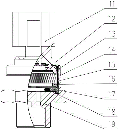
technical field [0001] The invention relates to a pressure sensor, in particular to a pressure sensor suitable for air conditioners. Background technique [0002] The structure of the existing air-conditioning pressure sensor is as follows: figure 1 As shown, it includes connector 11 , flexible circuit board assembly 12 , ceramic capacitive pressure core 13 , stainless steel shell 14 , insulating paper 15 , sealing pad 6 , sealing ring retaining ring 17 , O-ring 18 , and housing 19 . The pressure medium enters the interior of the sensor through the small hole on the shell 19, passes through the small hole on the stainless steel shell 14 and acts on the ceramic capacitor pressure core 13, and the ceramic capacitor pressure core 13 converts the pressure into an electrical signal and transmits it to the flexible circuit board assembly 12. After signal processing by the flexible circuit board assembly 12 , the pressure signal is output through the connector 11 . [0003] There...

Claims


Application Information

Patent Timeline
Patent Type & Authority Applications(China)
IPC IPC(8): G01L19/14G01L19/06
Inventor 张燕亮陈竹健夏状东张林伟姚福龙金波
Owner NINGBO CRRC TIMES TRANSDUCER TECH CO LTD
Learn More