Housing of multichannel speed sensor mounted at locomotive axle end

A speed sensor, multi-channel technology, applied in instruments, speed/acceleration/shock measurement, speed/acceleration/shock meter detailed information, etc., can solve the hidden danger of insulation voltage performance, cumbersome phase debugging steps, and inclined printed board components. and other problems, to achieve the effect of simple tolerance control, solving production bottleneck problems, and convenient phase adjustment

Active Publication Date: 2015-11-11
NINGBO CRRC TIMES TRANSDUCER TECH CO LTD
View PDF7 Cites 9 Cited by
  • Summary
  • Abstract
  • Description
  • Claims
  • Application Information

AI Technical Summary

Problems solved by technology

[0004] 1. The existing shell is assembled with set screw 1, mounting base 2, sensor head shell 3, and tail pipe 5. The size of some components needs to be obtained by assembling two or more parts, such as figure 2 As shown, the tolerance of the dimension H in the figure is obtained by accumulating tolerances of the matching dimensions of the sensor head housing 3 and the mounting seat 2, which requires very high machining accuracy for the sensor head housing 3 and the mounting seat 2 to realize the transmission. The sensor head shell 3 and the mounting seat 2 are mixed, which is difficult to process, and the size is prone to out-of-tolerance phenomena during production. At the same time, during product assembly and debugging, the size H will be screwed in by the tail pipe 5 and the taper set screw 1. Changes due to other reasons; in addition figure 2 The mating surface 21 of the seat on the middle mounting base 2 and the outer cylindrical surface of the sensing head housing 3 need to ensure high coaxiality, but there must be a gap at the joint between the sensing head housing 3 and the mounting base 2, so that the coaxiality is relatively low. Low
[0005] 2. When the printed board assembly 4 is loaded into the sensor head housing 3 and filled with glue, there is no clamping and fixing structure. Due to the long printed board, the problem of tilting and offset of the printed board assembly will occur during the curing process of the glue. Cause hidden dangers in the insulation and voltage resistance performance of the product
[0014] The above-mentioned phase debugging steps are cumbersome. To complete the phase debugging, the above seven steps need to be repeated many times, and the production efficiency is low.

Method used


Image

  • Housing of multichannel speed sensor mounted at locomotive axle end
  • Housing of multichannel speed sensor mounted at locomotive axle end
  • Housing of multichannel speed sensor mounted at locomotive axle end

Examples


Embodiment Construction

[0031] The present invention will be further described below in conjunction with the embodiments of the accompanying drawings.

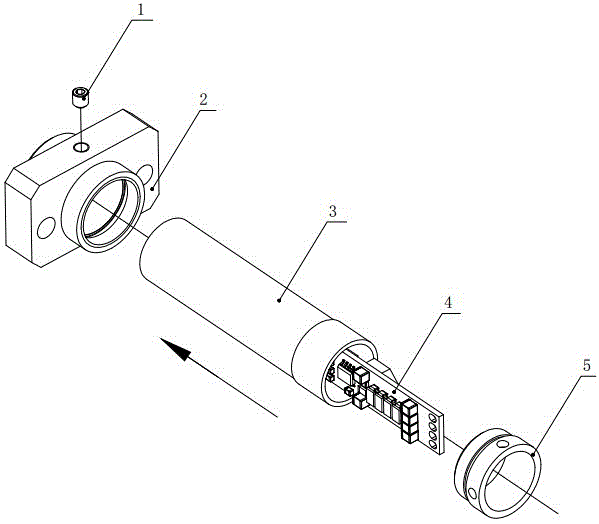
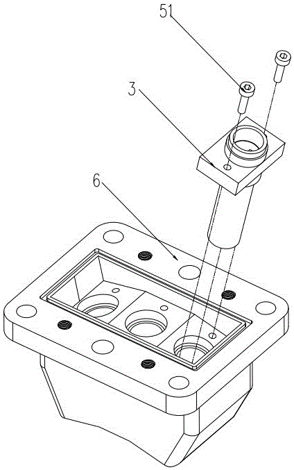
[0032] Such as Figure 5 As shown, the multi-channel locomotive shaft end speed sensor housing includes an integrated sensor head housing 8 , a printed board assembly 4 , and a printed board assembly fixing ring 7 .

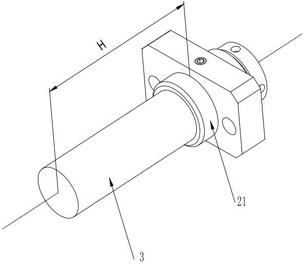
[0033] The above-mentioned one-piece sensor head housing 8 is a cylinder, which includes a closed head 81, a cavity 85 for accommodating the printed board assembly 4, and a tail end 84. The tail end 84 is a positioning ring, and a positioning groove is arranged on the positioning ring. 82, used to fix the fixing ring 7 of the printed board assembly.

[0034] The above-mentioned printed board fixing ring 7 includes a ring that can be sleeved on the tail end of the integrated sensor head housing, and the inner ring of the ring is symmetrically provided with a protrusion 73 corresponding to the positioning groove 82 at the tail end of the...


PUM


Abstract

The invention discloses a housing of multichannel speed sensor mounted at locomotive axle end. The casing includes an integral sensing head external casing, a printed board component, and a printed board component fixing piece. The integral sensing head external casing includes a cylinder main body which has an enclosed head portion and a middle portion and a tail end, and the middle portion is a cavity for receiving the printed board component and the tail end is provided with a positioning circular ring. The positioning circular ring is provided with a raised portion or a recessed groove, and correspondingly the printed board component fixing piece is provided with a recessed groove or a raised portion. The printed board component sleeves on the circular ring at the rear end of the cylinder main body. The recessed groove or the raised portion on the printed board component fixing piece accepts or is inserted to the raised portion or the recessed groove on the positioning circular ring so as to position the printed board component fixing piece. The printed board component fixing piece is also provided with a groovefor fixing the printed board component. The two sides of the printed board component are inserted to the groove and thus are secured. The circumference of the cylinder main body is provided with positioning components thereon. The positioning components each are provided with a concentric arc chute which is for connection with the cylinder main body. The casing herein has the advantages of simple structure, high production efficiency, and excellent precision.

Description

technical field [0001] The invention relates to an inner casing of a shaft end rotational speed sensor, which is a core component inside the sensor and is in direct contact with a printed board. Background technique [0002] The housing of the existing multi-channel locomotive shaft end speed sensor is as follows: figure 1 As shown, it includes a cone set screw 1, a mounting seat 2, a sensor head housing 3, a printed board assembly 4, and a tailpipe 5. The printed board assembly 4 is loaded into the sensor head housing 3 and then filled with an appropriate amount of glue to fix it. Then put the sensing head shell 3 into the mounting seat 2 according to the assembly direction shown in the figure, rotate the sensing head shell 3 to complete the phase adjustment, screw the cone set screw 1 into the mounting seat 2 to fix the sensing head shell 3, Finally, the tail pipe 5 is screwed into the mounting base 2 until the front end of the tail pipe 5 touches the tail end of the sens...

Claims


Application Information

Patent Timeline
Patent Type & Authority Applications(China)
IPC IPC(8): G01P1/02
Inventor 陈增贤张燕亮杨敏
Owner NINGBO CRRC TIMES TRANSDUCER TECH CO LTD
Why Eureka
Try Eureka