
Zoom lenses and zoom lens modules

A zoom lens and lens technology, applied in the field of zoom lenses and zoom lens modules, can solve the problems of not being able to meet the needs of users, zoom lenses not meeting the needs of large apertures, insufficient luminous flux, etc., and achieve the effect of good optical imaging quality

Active Publication Date: 2018-02-16
YOUNG OPTICS
View PDF6 Cites 0 Cited by
  • Summary
  • Abstract
  • Description
  • Claims
  • Application Information

AI Technical Summary

Problems solved by technology

[0003] However, the current design of the periscope zoom lens is difficult to achieve high resolution, large aperture and wide viewing angle at the same time due to the difficulty in processing and limited by stricter tolerances.
In addition, when using a digital camera at night with a small aperture, it is easy to face the dilemma of insufficient luminous flux, more noise, and underexposure
For example, the F-numbers (F-number) of the apertures disclosed in US Patent No. 7466500 and US No. 7180684 are both above 3.5, so it is easy to face the problem of insufficient luminous flux
[0004] In addition, the zoom lens proposed in U.S. Patent No. 7,286,299 not only fails to meet the needs of a large aperture, but also has a small field of view (FOV) (2ω), which will lead to the shortcomings of narrowing the shooting range and insufficient luminous flux. Unable to meet user needs

Method used


Image

  • Zoom lenses and zoom lens modules
  • Zoom lenses and zoom lens modules
  • Zoom lenses and zoom lens modules

Examples


Embodiment Construction

[0050] The aforementioned and other technical contents, features and effects of the present invention will be clearly presented in the following detailed description of a preferred embodiment with reference to the drawings. The directional terms mentioned in the following embodiments, such as: up, down, left, right, front or back, etc., are only referring to the directions of the drawings. Accordingly, the directional terms are used to illustrate and not to limit the invention.

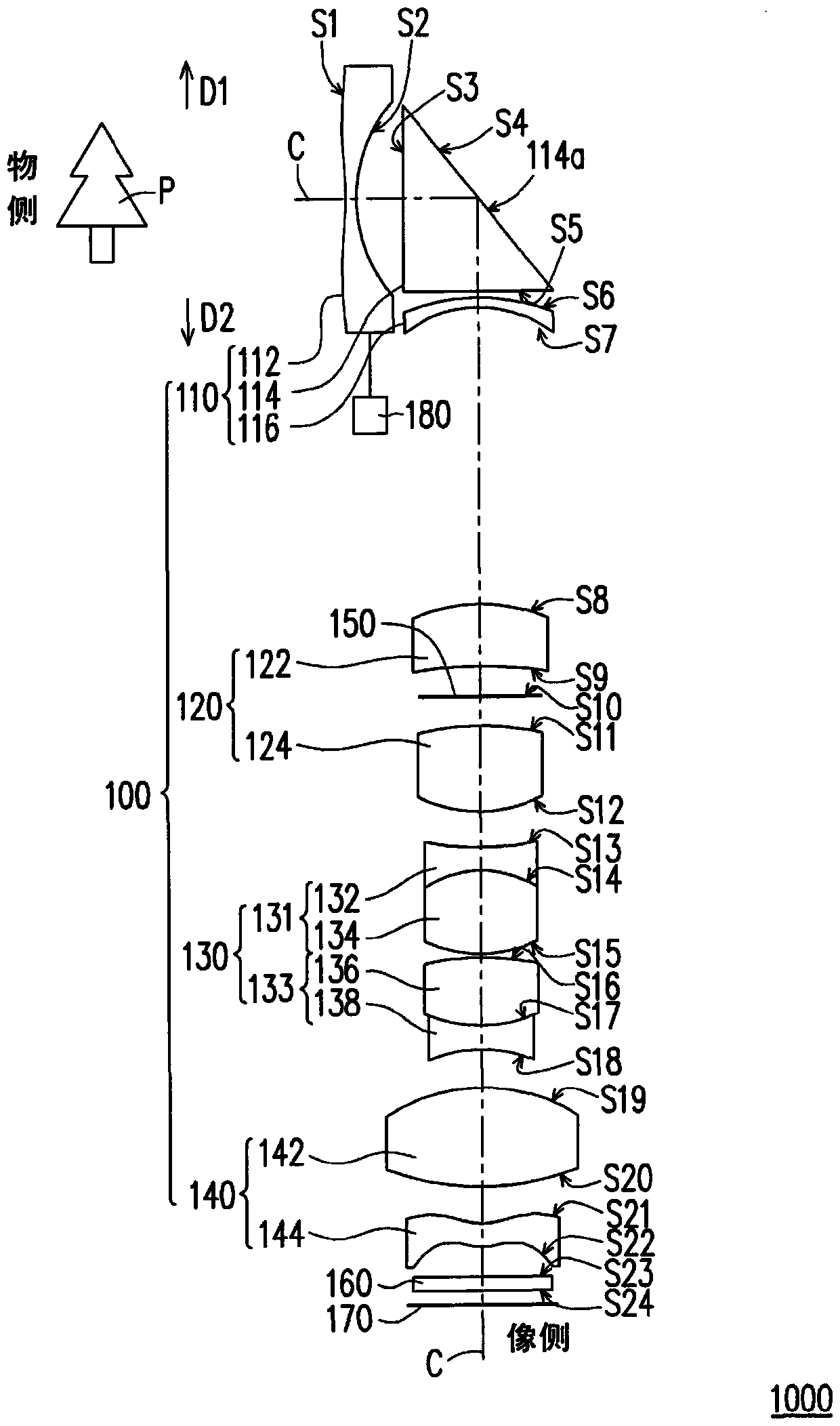
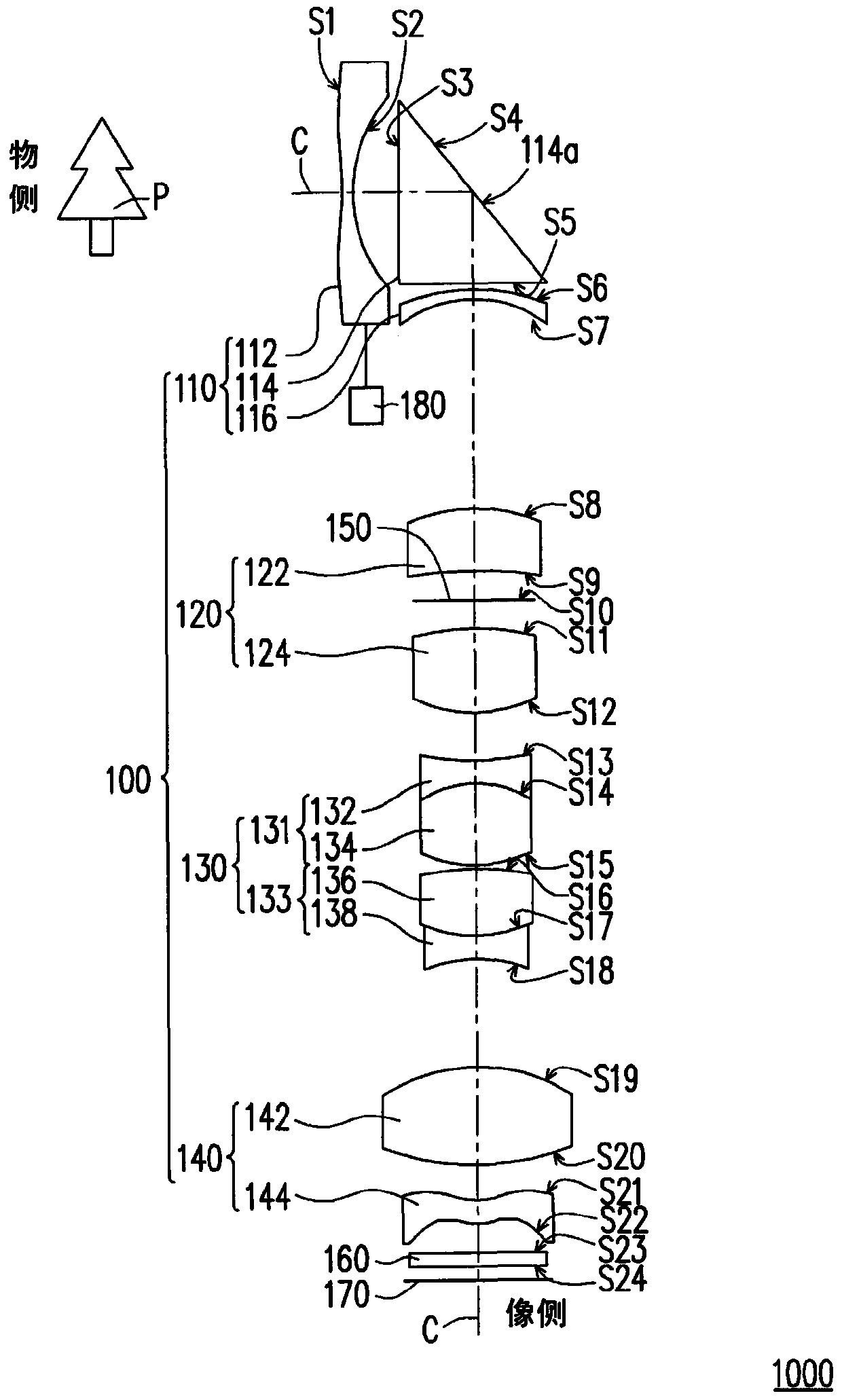
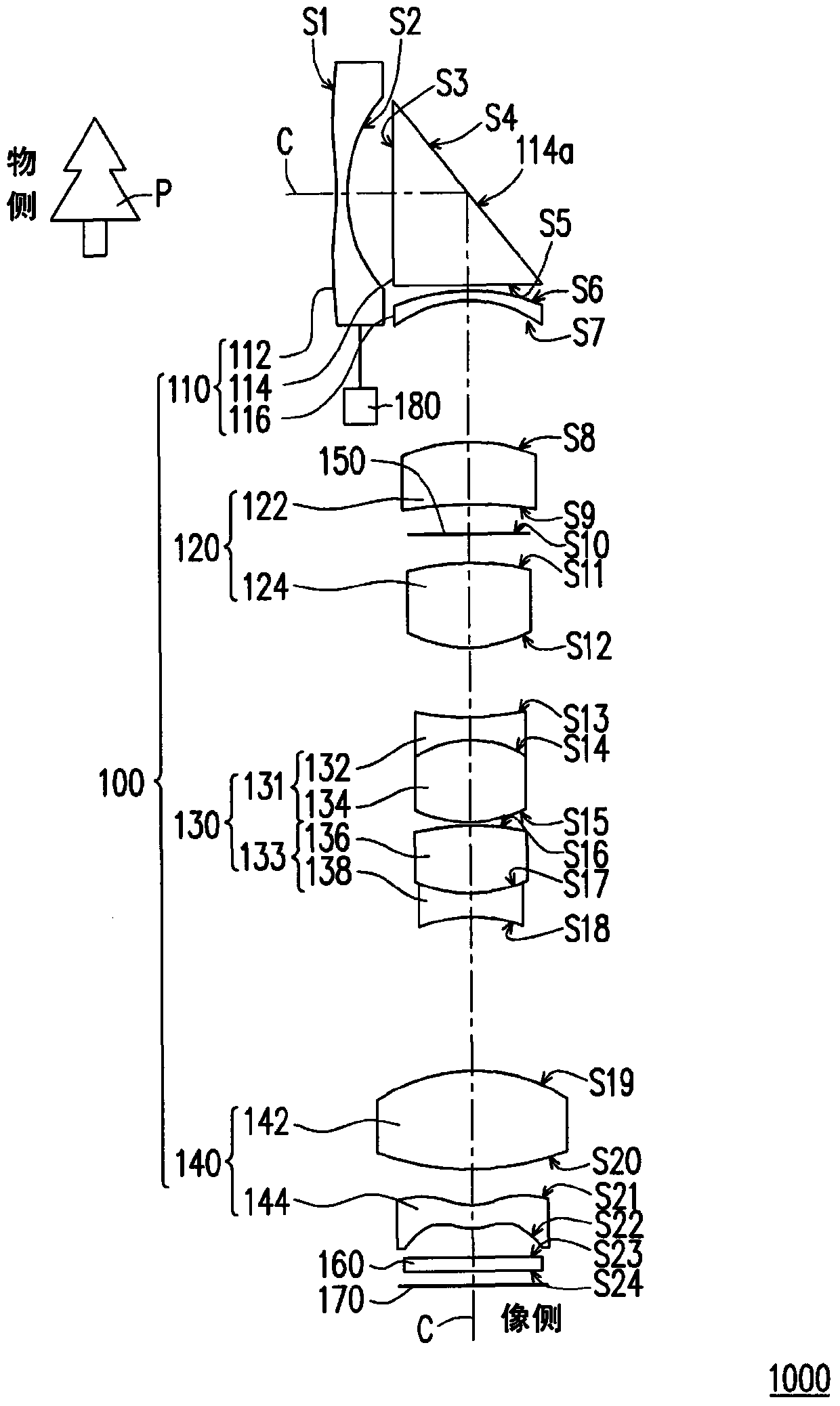
[0051] Figure 1A to Figure 1Dis a structural schematic diagram of a zoom lens module in an embodiment of the present invention under different zoom ratios, wherein Figure 1A Showing the structure of the zoom lens module at the wide-end (wide-end), Figure 1B Showing the structure when the zoom lens module is in the first intermediate position (middle), Figure 1C shows the structure of the zoom lens module in the second intermediate position, and Figure 1D The structure when the zoom lens module...


PUM


Abstract

A zoom lens and a zoom lens module are disclosed. The zoom lens is suitable for imaging a scenery of an object side to an imaging surface of an image side. The zoom lens comprises a first lens group, a second lens group, a third lens group and a fourth lens group. The first lens group is configured between the object side and the image side and possesses a negative diopter. The second lens group is configured between the first lens group and the image side and possesses a positive diopter. The third lens group is configured between the second lens group and the image side and possesses the negative diopter. The fourth lens group is configured between the third lens group and the image side. The zoom lens accords with the following formulas: 16>= C. R. A. (W) / ImgH>=10; and 15>= C. R. A. (T) / ImgH>= 7, wherein the C. R. A. (W) is an incidence angle of a zoom lens primary ray which irradiates to a largest field of a light detector when the zoom lens is in a wide angle end state; the C. R. A. (T) is an incidence angle of a zoom lens primary ray which irradiates to the largest field of the light detector when the zoom lens is in a telescopic end state; and the ImgH is a largest image height of the light detector.

Description

technical field [0001] The present invention relates to a lens and a lens module, and in particular to a zoom lens and a zoom lens module. Background technique [0002] With the advancement of modern video technology, in recent years, the demand for high-resolution, high-quality digital video camera (DVC) and digital camera (digital camera, DC) lenses has gradually increased, and is moving towards miniaturization and large aperture. Developed with a wide viewing angle. One of the core elements of these imaging devices is a zoom lens. The optical zoom of the zoom lens can make the far and near images clearly imaged. Therefore, the optical quality of the zoom lens is closely related to the image quality. In the fiercely competitive market, various manufacturers are committed to improving the quality of the zoom lens and reducing its production cost, so as to enhance the competitive advantage of the above-mentioned imaging devices. [0003] However, the current design of the ...

Claims


Application Information

Patent Timeline
Patent Type & Authority Patents(China)
IPC IPC(8): G02B15/177
Inventor 王国权洪国书陈信德
Owner YOUNG OPTICS
Learn More