Optical lens and manufacturing method thereof

An optical lens and mirror group technology, applied in optics, optical components, instruments, etc., can solve the problems of complex tolerance requirements of projection lens processing, difficult to achieve large aperture and high imaging quality at the same time, and achieve good optical imaging quality and low chromatic aberration. , the effect of low distortion

Pending Publication Date: 2021-06-18
YOUNG OPTICS
View PDF7 Cites 3 Cited by
  • Summary
  • Abstract
  • Description
  • Claims
  • Application Information

AI Technical Summary

Problems solved by technology

However, the projection lens with zoom function is complicated to process and is limited by strict tolerance requirements, so it is difficult to achieve the characteristics of large aperture and high imaging quality at the same time

Method used


Image

  • Optical lens and manufacturing method thereof
  • Optical lens and manufacturing method thereof
  • Optical lens and manufacturing method thereof

Examples


Embodiment Construction

[0019] The foregoing and other technical contents, features and functions of the present invention will be clearly presented in the following detailed descriptions of multiple embodiments with reference to the drawings. In addition, the terms "first" and "second" used in the following embodiments are used to identify the same or similar elements, and the directional terms such as "front" and "rear" are only for referring to the attached drawings The direction is not intended to limit the described elements.

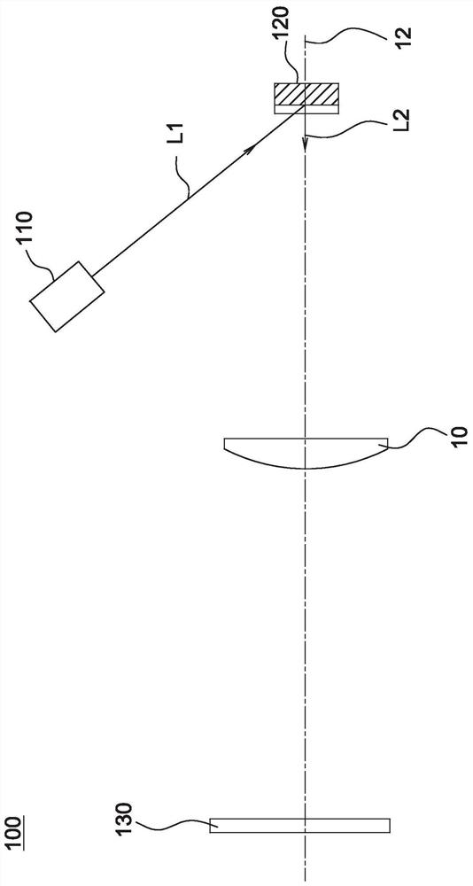
[0020] figure 1 It is a schematic diagram of the optical structure of the projection device 100 according to an embodiment of the present invention. Please refer to figure 1 , the projection device 100 of this embodiment includes an illumination unit 110 , a light valve 120 , a projection lens 10 and a screen 130 . The lighting unit 110 is used for providing the lighting beam L1. In this embodiment, the lighting unit 110 may be any device for illuminating the light va...


PUM


Abstract

An optical lens is used for receiving and projecting an image light beam and comprises a first lens group, a second lens group, a third lens group and a fourth lens group which are sequentially arranged from an amplification side to a reduction side, and an aperture arranged between the second lens group and the fourth lens group. When the optical lens is zoomed, the first lens group, the second lens group and the third lens group move relative to the light valve or the imaging surface of the optical lens, and the optical lens meets the following conditions: an image light beam firstly enters the fourth lens group, and the number of lenses with diopter is 9-16; a triplet lens and a doublet lens are arranged between the aperture and the lens closest to the reduction side. When the optical lens is a wide-angle end, the distance between lens surfaces with diopters on the outermost sides of the two ends of the optical lens along the optical axis of the optical lens is 85-110mm.

Description

technical field [0001] The invention relates to an optical lens and a manufacturing method thereof, in particular to a projection lens and a manufacturing method thereof. Background technique [0002] Among various types of display devices, the projection device has the characteristic of projecting a large-sized image frame several times larger than the surface area of ​​the device with a smaller device volume, so it has an irreplaceable advantage in the display field. Since the projection device projects the image beam converted by the light valve on the screen through the projection lens, the quality of the image is greatly affected by the quality of the projection lens. Therefore, the projection lens is a key optical element in the projection device. [0003] Generally speaking, the projection lens has the function of variable focal length. Utilizing the zoom function of the projection lens, the projection device can achieve the effect of zooming the image. Currently, ...

Claims


Application Information

Patent Timeline
Patent Type & Authority Applications(China)
IPC IPC(8): G02B15/16
CPCG02B15/16
Inventor 张硕杰陈信德王国权
Owner YOUNG OPTICS
Why Eureka
Try Eureka