
Alignment inspection device and method for liquid crystal display panel

A liquid crystal display panel and inspection equipment technology, applied in nonlinear optics, instruments, optics, etc., can solve the problems of light transmission path interference, diffuse reflection, refraction, inability to calculate alignment accuracy, etc. The effect of bit detection accuracy and high alignment detection accuracy

Active Publication Date: 2015-11-11
WUHAN CHINA STAR OPTOELECTRONICS TECH CO LTD
View PDF4 Cites 10 Cited by
  • Summary
  • Abstract
  • Description
  • Claims
  • Application Information

AI Technical Summary

Problems solved by technology

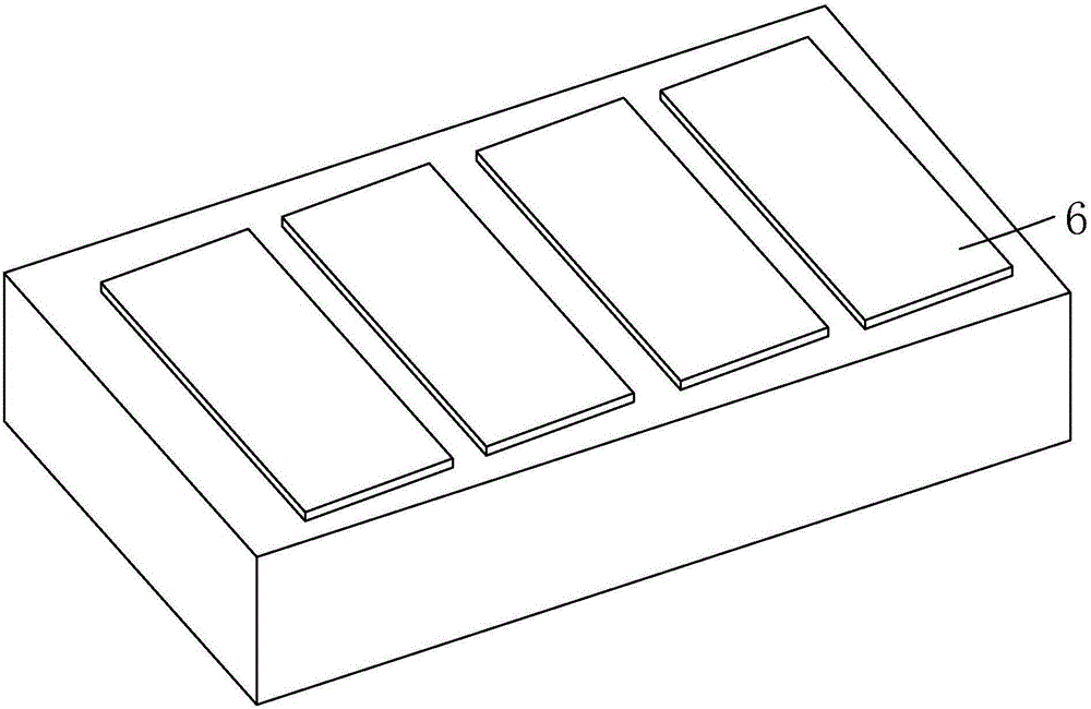
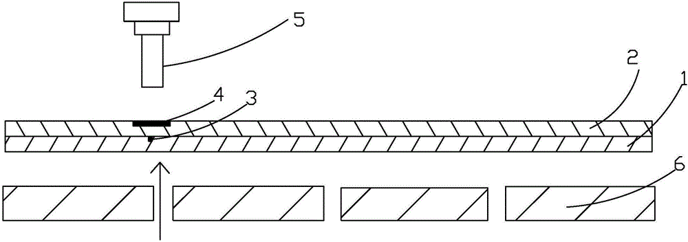
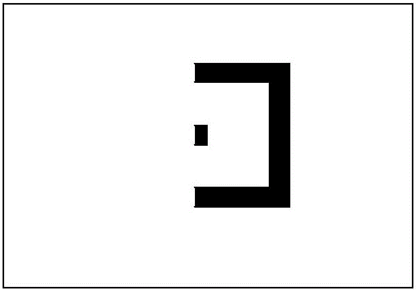
The existing alignment inspection equipment includes a light source, an alignment charge-coupled device (Charge-coupled Device, CCD) camera 5, and a plurality of glass fixed disks (GlassStage) 6, such as figure 1 As shown, a plurality of glass fixed disks 6 are arranged side by side in the inspection equipment, such as figure 2 As shown, during the alignment inspection, the light source is located under the glass fixed plate 6, that is, in the transmission lighting mode, the alignment CCD camera 5 captures the CF alignment marks respectively located on the CF substrate 1 and the TFT substrate 2 3. The TFT alignment mark 4, but when the TFT alignment mark 3 and the CF alignment mark 4 overlap with the edge of the glass fixed plate 6, the transmission path of the light will be disturbed, and the edge of the glass fixed plate 6 will be diffused. Reflection, refraction, etc., such as image 3 As shown, at this time, the alignment inspection equipment will not be able to accurately recognize the complete shape of the alignment mark, and thus cannot calculate the alignment accuracy

Method used


Image

  • Alignment inspection device and method for liquid crystal display panel
  • Alignment inspection device and method for liquid crystal display panel
  • Alignment inspection device and method for liquid crystal display panel

Examples


Embodiment Construction

[0038] In order to further illustrate the technical means adopted by the present invention and its effects, the following describes in detail in conjunction with preferred embodiments of the present invention and accompanying drawings.

[0039] The present invention firstly provides an alignment inspection device for a liquid crystal display panel, including a light source, an alignment CCD camera 50, and a transparent fixing plate 60 located below the alignment CCD camera 50;

[0040] The light source includes an upper light source (not shown) located above the transparent fixed plate 60, and a lower light source (not shown) located below the transparent fixed plate 60; Figure 4-6 As shown, a circle of reflective film 61 is provided on the edge of the lower surface of the transparent fixed plate 60 .

[0041] Specifically, the upper light source is a reflected light source, the lower light source is a transmitted light source, and the number of the transparent fixed disks 60...


PUM


Abstract

The invention provides an alignment inspection device and method for a liquid crystal display panel. The alignment inspection device for the liquid crystal display panel comprises light sources, an alignment CCD camera (50) and a transparent fixed disc (60) located below the alignment CCD camera (50); the light sources comprise the upper light source located above the transparent fixed disc (60) and the lower light source located below the transparent fixed disc (60); a circle of reflecting film (61) is arranged on the edge of the lower surface of the transparent fixed disc (60). As the upper light source and the lower light source provide a vertical illumination mode and a transmission illumination mode respectively, the alignment marker recognition rate of the alignment CCD camera can be effectively increased, and alignment detection accuracy of the alignment CCD camera can be effectively improved. According to the alignment inspection method for the liquid crystal display panel, when alignment markers are overlapped with the edge of the transparent fixed disc, by the adoption of the mode of combining vertical illumination and transmission illumination, the alignment marker recognition rate of the alignment CCD camera can be effectively increased, and the alignment detection accuracy is high.

Description

technical field [0001] The invention relates to the field of display technology, in particular to an alignment inspection device and an alignment inspection method for a liquid crystal display panel. Background technique [0002] In the field of display technology, flat-panel displays such as Liquid Crystal Display (LCD) and Organic Light Emitting Diode (OLED) have gradually replaced CRT displays, and are widely used in LCD TVs, mobile phones, personal digital assistants, digital cameras, computer screens or laptop screen etc. [0003] The display panel is an important part of the liquid crystal display and organic light emitting diode display. Taking the display panel of a liquid crystal display as an example, a liquid crystal display panel usually consists of a color filter substrate (CF, ColorFilter), a thin film transistor substrate (TFT, ThinFilmTransistor), and a liquid crystal (LC, LiquidCrystal) sandwiched between the color filter substrate and the thin film transis...

Claims


Application Information

Patent Timeline
IPC IPC(8): G02F1/13
CPCG02F1/1309G02F1/133354
Inventor 张勇李定良何恭育
Owner WUHAN CHINA STAR OPTOELECTRONICS TECH CO LTD
Learn More