Intelligent grouting system

An intelligent, grouting pump technology, applied in general control systems, control/regulation systems, non-electric variable control and other directions, can solve the problems of high labor intensity, tampering with grouting data, inaccurate proportions, etc. The effect of saving labor costs and ensuring personal safety

Active Publication Date: 2017-07-18
成都中大华瑞科技有限公司
View PDF6 Cites 0 Cited by
  • Summary
  • Abstract
  • Description
  • Claims
  • Application Information

AI Technical Summary

Problems solved by technology

2) The existing slurry mixing method has low efficiency, high labor cost, inaccurate mixing ratio, high labor intensity, time-consuming and labor-intensive
3) The existing grouting pumps output high pressure and constant power, which leads to energy waste, and manual operation of high pressure and high pressure valves is unsafe and easy to cause casualties
4) The traditional grouting process is all manually operated, which is not only inefficient, but also easily leads to human cheating, tampering with grouting data, and affecting the quality of grouting

Method used


Image

  • Intelligent grouting system
  • Intelligent grouting system
  • Intelligent grouting system

Examples


Embodiment 1

[0028] The intelligent grouting system of this embodiment is composed of the following parts, which will be described one by one with reference to the accompanying drawings.

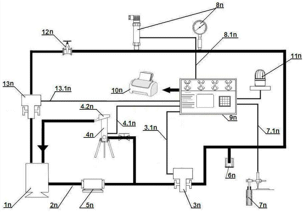
[0029] 1) see Figure 4 , set up a single-chip microcomputer control system 6, a keyboard 7, and a display 8. The single-chip microcomputer control system has an optocoupler isolation circuit 6.1, an A / D conversion 6.2, a single-chip microcomputer 6.3 and a communication port 6.7 which are sequentially connected along the input information transmission direction. Keyboard 7 is used for input setting, is connected with single-chip microcomputer keyboard interface 6.8. Display 8 is used for displaying data, and is connected with MCU display interface 6.9.

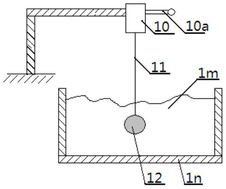
[0030] 2) On-line cement slurry hydrometer: see image 3 In the grouting detection and recording system, a tension sensor 10 is fixed above the grouting barrel 1n filled with the measured cement slurry 1m. The lower end of the tension sensor suspends a...

Embodiment 2

[0044] Embodiment 2: except that the following features are different from Embodiment 1, all the other are the same.

[0045]

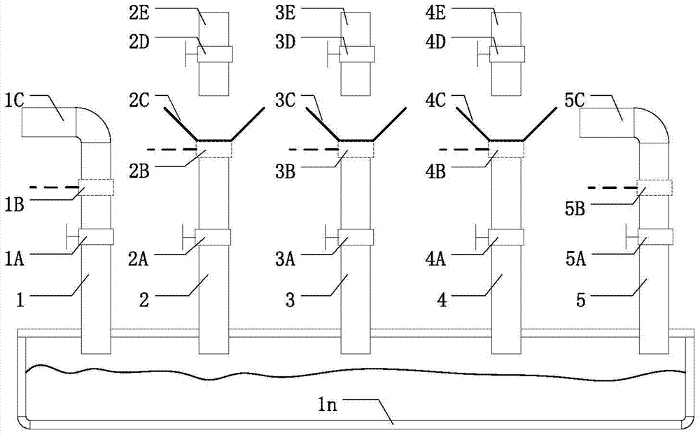
[0046] 1) see figure 2 , the following two pipelines and devices for inserting into water and thick slurry respectively are arranged and inserted in the pulping barrel 1n:

[0047] ① Insert the tap water pipe 1 equipped with the water pipe solenoid valve 1A, and the inlet end of the tap water pipe communicates with the tap water supply pipeline 1C equipped with the water flow sensor 1B. ⑤ Insert the thick slurry pipe 5 equipped with the thick slurry solenoid valve 5A, and the inlet end of the thick slurry pipe is connected with the thick slurry supply pipeline 5C equipped with the thick slurry flow sensor 5B.

[0048] 2) see Figure 4 , the above-mentioned water flow sensor 1B, thick slurry flow sensor 5B, tension sensor 10 (see image 3 ) The electrical signal output terminals of the three sensors in total are connected to the input terminal of...


PUM


Abstract

An intelligent grouting system is provided with a single chip microcomputer, a keyboard and a display. Pipelines provided with magnetic valves, sensors or electronic scales are inserted into a grout production barrel, wherein the pipelines are respectively loaded with water, cement powder, sand, a chemical additive, dense grout and so on therein; the proportioning and consumption of grout is controlled through programming, thus a grout proportioning efficiency is high, proportioning is accurate, and labor intensity is low. A frequency converter provided with a communication interface is added to a drive motor of a grouting pump, an input end of the single chip microcomputer is connected with a pressure sensor, an output end of the single chip microcomputer is connected with a high pressure valve and an alarm device; the power of the drive motor and the pressures of the pipelines are controllable, thereby saving electric energy; operating personnel are far away from the high-pressure pipes, thus security is achieved. A tension sensor of which an output end is connected with the single chip microcomputer is fixed over the grout production barrel, a metal weight immersed in cement grout is hanged on a lower end of the tension sensor; the single chip microcomputer continuously measures and displays the proportion, and adjusts the grout concentration in real time to ensure grouting quality, the frequency of cleaning is low. Through adoption of the intelligent grouting system, only grouting parameters need to be manually inputted, the subsequent operations such as grout proportioning and grouting are all automatically performed by the system, thereby saving time and labor. The intelligent grouting system is used for grouting construction of a hydropower station, especially at the places such as side slope and dam foundation.

Description

[0001] (1) Technical field: the present invention relates to a kind of grouting detection recording system with intelligent control. It is used for engineering measurement and quality control in hydropower station grouting engineering. It belongs to capacity and flow measurement (G01F). [0002] (two) background technology: [0003] Grouting works are generally used in power station dam construction. Grouting refers to pouring cement, mortar and other substances into the embankment and foundation of the dam of the power station to strengthen the firmness and improve the anti-seepage performance. Therefore, the quality of grouting will determine the overall quality of the power station dam. [0004] The general layout of the grouting detection and recording system of the existing hydropower station figure 1 : In order to detect and record values ​​such as the flow rate, density, pressure, lift, etc. of the grout poured into the grouting hole 6n, a grouting barrel 1n, a grouti...

Claims


Application Information

Patent Timeline
Patent Type & Authority Patents(China)
IPC IPC(8): G05D29/00G05B19/048
Inventor 蒋小春
Owner 成都中大华瑞科技有限公司
Why Eureka
Try Eureka