Manufacturing method and manufacturing equipment of optical fiber prefabricated rod

A technology for optical fiber preforms and manufacturing equipment, which is applied in glass manufacturing equipment, manufacturing tools, etc., can solve problems such as inability to adjust gas flow in real time, and achieve the effect of improving product quality, reasonable design, and preventing significant changes in density

Active Publication Date: 2013-08-14
ZHONGTIAN TECH ADVANCED MATERIALS CO LTD +2
View PDF5 Cites 13 Cited by
  • Summary
  • Abstract
  • Description
  • Claims
  • Application Information

AI Technical Summary

Problems solved by technology

The present invention can overcome the problem that the current process cannot adjust the gas flow rate in real time and precisely control the powder rod density, and proposes a method based on the surface temperature acquisition technology, real-time adjustment of the gas flow rate, and precise control of the powder rod density method and its manufacturing equipment , which can effectively prevent the powder rod from cracking due to a large density gradient, thereby improving product quality

Method used


Image

  • Manufacturing method and manufacturing equipment of optical fiber prefabricated rod
  • Manufacturing method and manufacturing equipment of optical fiber prefabricated rod
  • Manufacturing method and manufacturing equipment of optical fiber prefabricated rod

Examples


Embodiment 1

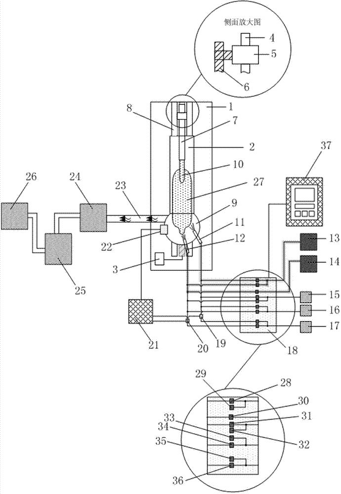
[0067] A quartz target rod 10 with a length of 500 mm is installed on the metal suspender 7, and the SiCl with an initial flow rate of 0.1 g / min 4 , 0.01g / min of GeCl 4 , Ar at 1.0L / min, O at 5.0L / min 2and 3.0L / min of H 2 Pass into the quartz blowtorch 212 to generate SiO through flame hydrolysis reaction 2 、GeO 2 , attached to the lower end of the quartz target rod 10 to form a core layer. Feed SiCl with an initial flow rate of 0.1 g / min into the quartz blowtorch 11 4 , Ar at 1.0L / min, O at 15.0L / min 2 and 10.0L / min of H 2 , to generate SiO by flame hydrolysis 2 , forming the cladding of the preform. The flow settings of each stage are as follows in Table 1:

[0068]

[0069] Table 1

[0070] Such as figure 2 , the rotation of the metal suspender 7 is controlled by the chuck 5, and the metal suspender 7 pulls the quartz target rod 10 up along the guide rail 8, wherein the rotation speed is controlled at 10rpm, and the lifting speed is controlled at 35mm / h. Th...

Embodiment 2

[0074] A quartz target rod 10 with a length of 500 mm is installed on the metal suspender 7, and the SiCl with an initial flow rate of 0.1 g / min 4 , 0.01g / min of GeCl 4 , Ar at 1.0L / min, O at 6.0L / min 2 and 4.0L / min of H 2 Pass into the quartz blowtorch 212 to generate SiO through flame hydrolysis reaction 2 、GeO 2 , attached to the lower end of the quartz target rod 10 to form a core layer. Introduce SiCl with an initial flow rate of 0.1g / min into the quartz blowtorch-11 4 , Ar at 1.0L / min, O at 20.0L / min 2 and 15.0L / min of H 2 , to generate SiO by flame hydrolysis 2 , forming the cladding of the preform. The flow setting of each stage is as follows in Table 2:

[0075]

[0076] Table 2

[0077] Such as figure 2 , the rotation of the metal suspender 7 is controlled by the chuck 5, and the metal suspender 7 pulls the quartz target rod 10 up along the guide rail 8, wherein the rotation speed is controlled at 10rpm, and the lifting speed is controlled at 35mm / h. ...


PUM


Abstract

The invention relates to a manufacturing method and manufacturing equipment of an optical fiber prefabricated rod, belongs to the field of manufacturing of an optical fiber prefabricated rod, and in particular relates to the method and the equipment which are used for collecting the surface temperature of a powder rod head by utilizing the infrared thermal imaging technology and participate in the controlling of the gas flow. By utilizing the method, the gas flow can be adjusted in real time, so that the density of the powder rod can be controlled accurately; and thus the cracking of the powder rod, caused by the large density gradient, is avoided. Therefore, the product quality is improved. The equipment comprises a tower body, a prefabricated rod depositing cavity body, a motor 1, a motor 2, a clamping disk, a lead screw, a metal hanging rod, a guiding rail, a quartz cavity body, a quartz target rod, a quartz spraying lamp 1, a quartz spraying lamp 2, a SiCl4 raw material tank, a GeCl4 material jar, a liquid Ar storage tank, a liquid O2 storage tank, a H2 storage tank, a gas control cabinet, an electromagnetic valve 1, an electromagnetic valve 2, a CPU (Central Processing Unit), a thermal infrared imager, an exhaust duct, a front treating tower, an electric dust-removing tower and a washing tower.

Description

technical field [0001] The invention relates to a method and equipment for manufacturing an optical fiber preform, and relates to the field of optical fiber preform manufacturing. Specifically, it is a method and equipment for collecting the surface temperature of a powder rod head using infrared thermal imaging technology and participating in the control of gas flow. The method can be used to adjust the gas flow rate in real time, so as to realize the precise control of the powder rod density, prevent the powder rod from cracking due to the large density gradient, and improve the product quality. Background technique [0002] At present, the flow rate of the gas used in the axial vapor deposition method is mainly controlled by a mass flow controller (MFC for short). MFC controls the flow rate by pre-setting several stages and assigning a constant flow rate to each stage. During the deposition process of powder rods, the gas is supplied according to the preset flow rate. Th...

Claims


Application Information

Patent Timeline
IPC IPC(8): C03B37/018
CPCC03B37/01413
Inventor 谢康陶伟钱宜刚吴椿烽沈一春
Owner ZHONGTIAN TECH ADVANCED MATERIALS CO LTD
Why Eureka
Try Eureka