Fingerprint identification module

A fingerprint recognition module and fingerprint recognition technology, applied in character and pattern recognition, acquisition/organization of fingerprints/palmprints, digital data authentication, etc. Improve the service life and play a protective effect

Active Publication Date: 2015-11-11
MICROARRAY MICROELECTRONICS CORP LTD
View PDF3 Cites 24 Cited by
  • Summary
  • Abstract
  • Description
  • Claims
  • Application Information

AI Technical Summary

Problems solved by technology

[0003] The fingerprint identification module disclosed in the prior art includes an electrical mechanism (the electrical mechanism includes a fingerprint identification chip and a circuit board), but no independent mechanical mechanism is provided, and the electrical mechanism is directly fixed between the upper cover and the lower cover during manufacture. , because the upper and lower end faces of the electrical mechanism are fixedly connected to the upper and lower cover plates respectively, when in use, the force applied by the user's finger to press the fingerprint recognition module is directly transmitted to the electrical mechanism, which may easily lead to mechanical damage of the electrical mechanism or cause electrical mechanism damage. The conductive material between the various components is loose, which leads to poor contact. The above faults will directly affect the service life of the fingerprint identification module.
[0004] In response to the above problems, fingerprint identification module manufacturers also have some existing solutions. For example, Apple adopts an evasive approach and does not solder on the back of the fingerprint identification chip, but connects to the circuit board from the side of the chip. This design leads to fingerprint identification. The manufacturing cost of the identification module is high, and the yield rate is low; the fingerprint module adopted by Huawei Mate7 uses a layer of foam under the fingerprint identification chip and maximizes the soldering area on the back of the chip. Essentially improving the pressure resistance of the chip, Huawei placed the fingerprint module on the back of the mobile phone that is not often under pressure. At the same time, because of its large size, it is not suitable for industrial design of small and medium-sized mobile phones.

Method used


Image

  • Fingerprint identification module
  • Fingerprint identification module
  • Fingerprint identification module

Examples


Embodiment 1

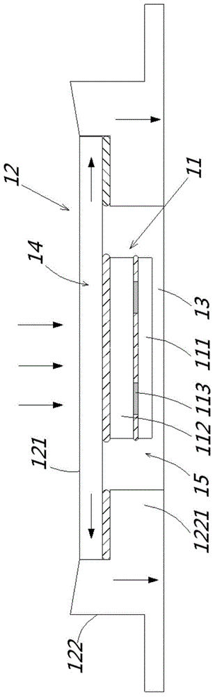
[0036] Please refer to figure 1 , figure 1 What is shown is a fingerprint identification module using TSV (ThroughSiliconVia, Through Silicon Via) packaging technology. The TSV packaging technology is an existing technology and will not be repeated here. The fingerprint identification module includes:

[0037] The electrical mechanism 11 and the mechanical mechanism 12 arranged on the periphery of the electrical mechanism 11 for distributing the pressure on the electrical mechanism 11 .

[0038] The mechanical mechanism 12 includes an upper cover plate 121 and a force transmission part 122 hollowed out in the middle. The upper cover plate 121 and the force transmission part 122 together form a storage space. In this embodiment, the bottom of the storage space An opening communicates with the hollowed-out middle part.

[0039] The electrical mechanism 11 includes a circuit board 111 and a fingerprint identification chip 112, the fingerprint identification chip 112 is used to...

Embodiment 2

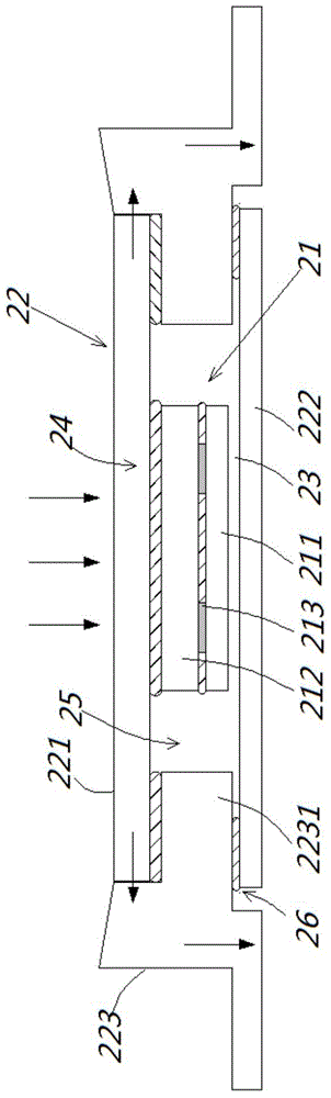
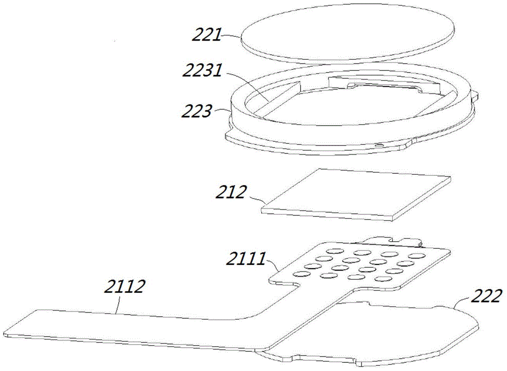
[0045] Please refer to Figures 2 to 3 , figure 2 , image 3 What is shown is a fingerprint identification module using TSV (ThroughSiliconVia, Through Silicon Via) packaging technology. The TSV packaging technology is an existing technology and will not be repeated here. The fingerprint identification module includes:

[0046] The electrical mechanism 21 and the mechanical mechanism 22 disposed on the periphery of the electrical mechanism 21 are used to divert the pressure on the electrical mechanism 21 .

[0047] The mechanical mechanism 22 includes an upper cover plate 221, a lower cover plate 222, and a hollowed-out force transmission part 223 in the middle. A support arm 2231 is provided on the inner wall of the hollowed-out middle part of the force transmission part 223. The support arm 2231 is connected to the The top end surface and the bottom end surface of the force transmission member 223 respectively form a step, and the receiving space is divided into a first ...

Embodiment 3

[0056] Please refer to Figure 4 , Figure 4 What is shown is a fingerprint identification module using plastic packaging technology. The plastic packaging technology is a prior art and will not be repeated here. The fingerprint identification module includes:

[0057] The electrical mechanism 31 and the mechanical mechanism 32 disposed on the periphery of the electrical mechanism 31 are used to divert the pressure on the electrical mechanism 31 .

[0058] Different from the fingerprint identification modules provided in Embodiments 1 and 2, the mechanical mechanism 32 in this embodiment is manufactured using plastic packaging technology, and the upper cover plate 321 and the force transmission part 322 in the mechanical mechanism 32 are of an integrated structure.

[0059] The electrical mechanism 31 includes a circuit board 311 and a fingerprint recognition chip 312 arranged on the circuit board 311, and the fingerprint recognition chip 312 is used for collecting fingerpri...


PUM


Abstract

The invention discloses a fingerprint identification module. The fingerprint identification module comprises an electrics mechanism and a mechanics mechanism, and the mechanics mechanism is arranged at the periphery of the electrics mechanism and is used for diverting the pressure applied onto the electrics mechanism. The mechanics mechanism comprises an upper cover plate and a force conduction part, wherein the middle part of the force conduction part is hollowed out. The upper cover plate is arranged at the top of the force conduction part and forms an accommodation space together with the force conduction part. The electrics mechanism comprises a circuit board and a fingerprint identification chip. The circuit board comprises an extension part and a connection part. The fingerprint identification chip is arranged in the accommodation space and is electrically connected with the connection part via a conductive element. The end surface of the top of the fingerprint identification chip is fixedly connected with the end surface of the bottom of the upper cover plate. The horizontal height of the end surface of the bottom of the connection part is higher than the horizontal height of the end surface of the bottom of the mechanics mechanism. Compared with the prior art, the pressure applied onto the electrics mechanism is dispersed by the mechanics mechanism. In this way, during the usage process, the electrics mechanism is well protected. Therefore, the service life of the fingerprint identification module is obviously prolonged.

Description

technical field [0001] The invention relates to the technical field of manufacturing and packaging of fingerprint identification modules. Background technique [0002] Since the fingerprint has characteristics such as lifelong invariance and uniqueness, the identity of the user can be accurately and reliably identified by identifying the fingerprint. The fingerprint identification module is a device that uses fingerprint identification technology to obtain the user's fingerprint image conveniently and quickly, and then identifies the user's identity. [0003] The fingerprint identification module disclosed in the prior art includes an electrical mechanism (the electrical mechanism includes a fingerprint identification chip and a circuit board), but no independent mechanical mechanism is provided, and the electrical mechanism is directly fixed between the upper cover and the lower cover during manufacture. , because the upper and lower end faces of the electrical mechanism a...

Claims


Application Information

Patent Timeline
Patent Type & Authority Applications(China)
IPC IPC(8): G06K9/00G06V10/147
CPCG06V40/1329G06V40/1306H01L23/562H01L23/3121G06V10/147G06V40/12H01L23/28G06F21/32H05K1/18H05K2201/10151
Inventor 李扬渊丁绍波
Owner MICROARRAY MICROELECTRONICS CORP LTD
Why Eureka
Try Eureka