Check patentability & draft patents in minutes with Patsnap Eureka AI!

Solder strip pulling device and method

A technology for welding strips and pressure welding strips is applied in the field of solar cell manufacturing equipment, which can solve the problems of long consumption time of drawing welding strips, affecting the welding efficiency of battery strings, and time-consuming drawing welding strips, etc., so as to improve handling efficiency and improve welding efficiency. Efficiency, the effect of improving production efficiency

Active Publication Date: 2015-11-11
WUXI LEAD INTELLIGENT EQUIP CO LTD
View PDF4 Cites 9 Cited by
  • Summary
  • Abstract
  • Description
  • Claims
  • Application Information

AI Technical Summary

Problems solved by technology

[0003] This method has the following disadvantages: it takes a long time to pull the welding ribbon, because the pulling of the welding ribbon, the cutting of the welding ribbon and the delivery of the cut welding ribbon to the set position are continuous, the next action can only be realized after the previous action is completed Therefore, it takes a long time to pull the welding ribbon, which will eventually affect the efficiency of battery string welding

Method used


Image

  • Solder strip pulling device and method
  • Solder strip pulling device and method

Examples


Embodiment Construction

[0022] The present invention will be further described below in conjunction with specific drawings and embodiments.

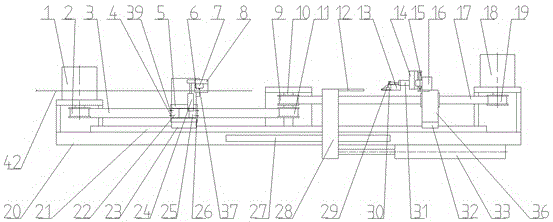
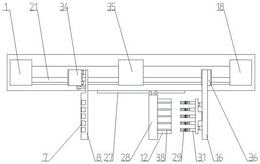
[0023] As shown in the figure, the present invention includes a bottom plate 20, a first line rail 21, a first strip-drawing device, and the first strip-drawing device and the first line rail 21 are respectively installed on the bottom plate 20. After the first strip-drawing device A second strip-drawing device is installed on the side, and a guiding strip device is provided between the first strip-drawing device and the second strip-drawing device, and the guiding strip device includes a guide plate 12, a second line rail 27, a fifth Mounting seat 28, electric cylinder 33, wherein, electric cylinder 33 is fixed on base plate 20, and the output end of electric cylinder 33 connects the 5th mounting seat 28, and the side end of the 5th mounting seat 28 is fixedly set guide plate 12, and guide plate 12 is arranged on the surface There are at least two guide slots ...


PUM


Abstract

The invention relates to a solder strip pulling device and method, and the device comprises a bottom plate, a first wire rail, and a first solder strip pulling apparatus. The first solder strip pulling apparatus and the first wire rail are respectively disposed on the bottom plate. The rear side of the first solder strip pulling apparatus is provided with a second solder strip pulling apparatus, and a guide solder strip apparatus is disposed between the first solder strip pulling apparatus and the second solder strip pulling apparatus. The first solder strip pulling apparatus comprises a first moving mechanism and a solder strip pressing mechanism, wherein the solder strip pressing mechanism can achieve the compression of a solder strip. The first moving mechanism can enable the solder strip pressing mechanism to move back and forth along the first wire rail, and is used for pulling the solder strip clamped by the solder strip pressing mechanism to a set position, or conveying the solder strip pressing mechanism to a solder strip grabbing position. The second solder strip pulling apparatus comprises a second moving mechanism and a clamping jaw mechanism, wherein the clamping jaw mechanism can achieve the clamping of the solder strip. The second moving mechanism can enable the clamping jaw mechanism to move back and forth along the first wire rail, and is used for conveying the clamping jaw mechanism to the position of the solder strip pressing mechanism and conveying the solder strip clamped by the solder strip pressing mechanism to the set position. The device is ingenious and reasonable in structure, is simple in structure, and can improve the pulling efficiency of the solder strip.

Description

technical field [0001] The invention relates to a welding ribbon pulling device and a welding ribbon pulling method, and belongs to the technical field of solar cell sheet manufacturing equipment. Background technique [0002] In the manufacturing process of solar cell modules, the cells need to be welded into strings through ribbons, and the transfer efficiency of the ribbons directly affects the welding efficiency of the cells. The current ribbon handling method uses a single ribbon transport mechanism to pull the fixed-length ribbon. After the cutting device cuts the ribbon, the ribbon conveyor mechanism continues to transport the cut ribbon to the surface of the cell. [0003] This method has the following disadvantages: it takes a long time to pull the welding ribbon, because the pulling of the welding ribbon, the cutting of the welding ribbon and the delivery of the cut welding ribbon to the set position are continuous, the next action can only be realized after the pr...

Claims


Application Information

Patent Timeline
IPC IPC(8): H01L31/18
CPCH01L31/1876Y02P70/50
Inventor 王燕清胡彬姜勇
Owner WUXI LEAD INTELLIGENT EQUIP CO LTD
Features
  • R&D
  • Intellectual Property
  • Life Sciences
  • Materials
  • Tech Scout
  • Unparalleled Data Quality
  • Higher Quality Content
  • 60% Fewer Hallucinations
Learn More