Slot array antenna with dielectric slab for electrical control of beam down-tilt

A technology of slot array antenna and dielectric board, which is applied in the direction of slot antenna, antenna, antenna array, etc.

A technology of slot array antenna and dielectric board, which is applied in the direction of slot antenna, antenna, antenna array, etc.

CN105048104AInactive Publication Date: 2015-11-11PYRAS TECH

Image

  • Slot array antenna with dielectric slab for electrical control of beam down-tilt
  • Slot array antenna with dielectric slab for electrical control of beam down-tilt
  • Slot array antenna with dielectric slab for electrical control of beam down-tilt

Examples


Embodiment Construction

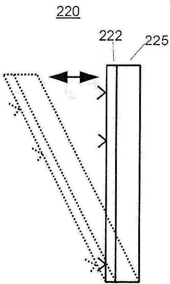
[0021] The presence of dielectric material within a waveguide can affect the propagation constant of a signal traveling within the waveguide and correspondingly affect the change in phase of a signal propagating through the waveguide. The present invention takes advantage of this phenomenon by: constructing a slot array antenna with a dielectric plate that is rotatable along the longitudinal axis of the slot array antenna; The dielectric plates are angularly positioned so as to affect the propagation constant and correspondingly the signal phase. Positioning the dielectric plate substantially orthogonal to the electric field produces substantially no change in propagation constant and signal phase, while positioning the dielectric plate substantially parallel to the electric field produces the strongest change in propagation constant and signal phase. Different angles of the dielectric plate to the electric field can impart corresponding different phases to the signal, and thu...


PUM


Abstract

A slot array antenna includes a waveguide slot body and a dielectric slab. The waveguide body includes one or more walls that define a waveguide aperture, the waveguide aperture extending along a longitudinal axis of the waveguide slot body. The waveguide slot body includes a plurality of slots disposed on one or more walls of the waveguide slot body. The dielectric slab is disposed within the waveguide aperture and extends along the longitudinal axis of the waveguide slot body. The dielectric slab is rotatable about the longitudinal axis within the waveguide aperture.

Description

[0001] Cross References to Related Applications [0002] This application claims the benefit of U.S. Provisional Application No. 61 / 975,826, filed April 6, 2014, entitled "Slot Array Base Station Antenna with Electrical Control of Down-Tilt Beam," which states The contents of the US Provisional Application are incorporated herein by reference in their entirety for all purposes. technical field [0003] The present invention relates to waveguide antennas, and more particularly to dielectrically loaded waveguide antennas. Background technique [0004] Base station antennas need to control beam downtilt for the radiation pattern of their systems in order to vary the coverage area of โ€‹โ€‹those systems. This variability is necessary because different beam downtilt angles will be required depending on the location and height of the base station and desired coverage area. figure 1 A base station antenna system 110 is illustrated with two different degrees of beam or radiation pat...

Claims


Application Information

Patent Timeline
11 Nov 2015
Publication
CN105048104A
IPC
H01Q21/00; H01Q13/10
CPC
H01Q3/04; H01Q13/18; H01Q21/0043
Inventors
้™ˆๆ˜Ž่พ‰