
Method and system for measuring resonant frequency of loudspeaker part

A resonant frequency and measurement system technology, applied in the direction of electrical components, etc., can solve the problems of large measurement errors, the inability to set the vibration amplitude of the measured diaphragm, etc., and achieve reliable measurement results

Active Publication Date: 2015-11-11
ZHEJIANG ELECTRO ACOUSTIC R&D CENT CAS +1
View PDF6 Cites 24 Cited by
  • Summary
  • Abstract
  • Description
  • Claims
  • Application Information

AI Technical Summary

Problems solved by technology

However, this method does not fully consider the influence of the resonant frequency of the excitation sound source itself and the cavity formed by the measured diaphragm and the excitation sound source on the measurement results. Diaphragms with relatively close frequencies will produce large measurement errors
[0007] In addition, since the resonant frequency of the speaker diaphragm is different at different amplitudes, that is, the use of different sizes of force to excite the diaphragm will result in different resonant frequencies. When using the above method and traditional equipment to measure, it is impossible to set The vibration amplitude of the tested diaphragm, even if different users use the same type of equipment to measure, the results are not the same, which often leads to conflicts between the diaphragm supplier and the purchaser
[0008] Similar problems also exist in the measurement of the resonant frequency of the speaker cone and the damper by the above measurement method

Method used


Image

  • Method and system for measuring resonant frequency of loudspeaker part
  • Method and system for measuring resonant frequency of loudspeaker part
  • Method and system for measuring resonant frequency of loudspeaker part

Examples


Embodiment Construction

[0038] The present invention will be further described below in conjunction with the accompanying drawings and specific embodiments.

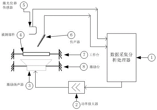
[0039] Such as figure 1 Shown, the present invention comprises: data acquisition and analysis processor (1), power amplifier (2), exciting sound source (speaker) (3), measured loudspeaker part (4), laser displacement transducer (5), microphone (6 ), operate the workbench (7) and motivate the workbench (8).

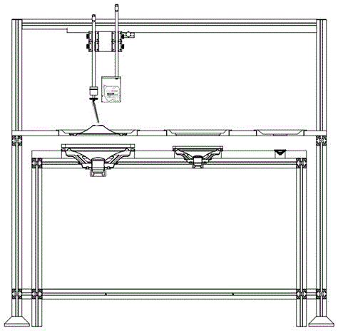
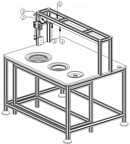
[0040] The operating table (7) table is embedded with a combined measuring fixture, which can fix the measured loudspeaker parts of different sizes; the excitation sound source (3) is installed on the exciting workbench (8) table, and the excitation workbench ( 8) Place it under the operating workbench (7) (the two workbench surfaces are parallel to each other, and there is no hard connection except that they are placed on the same ground), and the excitation sound source (3) below is directly facing the speaker component under test above....


PUM


Abstract

The present invention provides a method and a system for measuring the resonant frequency of a loudspeaker part. The system comprises a data acquisition and analysis processor, a power amplifier, an excitation sound source, a to-be-tested loudspeaker part, a laser displacement sensor, a microphone, an operation workbench, an excitation workbench, a tool clamp and the like. The excitation sound source is mounted on the top of the excitation workbench. The excitation workbench is arranged below the operation workbench. The downward-side excitation sound source is right facing the loudspeaker part above the excitation sound source. The laser displacement sensor and the microphone are fixed on an upward-side multifunctional bracket. The multifunctional bracket is capable of freely moving up and down, front and back, or left and right in a space above the top of the operation workbench. The data acquisition and analysis processor is used for generating excitation signals, acquiring, analyzing and processing measured signals, storing a measurement result and displaying the measurement result. Due to the adoption of the compensating means for the frequency response, the amplitude adjustment means for the vibration displacement and other means in an acoustic measurement environment, the resonant frequency of a diffuser (a vibrating diaphragm) with a centering disk can be accurately and conveniently measured.

Description

technical field [0001] The invention belongs to the application field of electroacoustic technology, and relates to a method and a system for measuring the resonant frequency of loudspeaker components. This system can be used to measure the resonant frequency of loudspeaker parts (including paper cone or diaphragm and centering strut), which can be widely used in the quality inspection (control) of loudspeaker parts and the design and development of loudspeakers. Background technique [0002] Significance of resonant frequency measurement of loudspeaker components: [0003] The loudspeaker is an electro-acoustic coupling system, which is mainly composed of three parts: magnetic circuit system, vibration system and acoustic load. The paper cone and centering piece of the loudspeaker are the core components of the loudspeaker vibration system, and the resonant frequency is one of its important technical indicators, which plays a vital role in the overall performance of the lo...

Claims


Application Information

Patent Timeline
IPC IPC(8): H04R29/00
Inventor 温周斌李宏斌王宇徐楚林金晶
Owner ZHEJIANG ELECTRO ACOUSTIC R&D CENT CAS
Learn More