Check patentability & draft patents in minutes with Patsnap Eureka AI!

High frequency generator circuit

A high-frequency generator and trigger circuit technology, which is applied in electric light sources, electrical components, lighting devices, etc., can solve the problems of high cost of high-frequency generator circuits, reducing the stability and service life of high-frequency generator circuits, etc.

Inactive Publication Date: 2015-11-11
王侃
View PDF5 Cites 0 Cited by
  • Summary
  • Abstract
  • Description
  • Claims
  • Application Information

AI Technical Summary

Problems solved by technology

[0002] In the existing high-frequency generator circuit, the controller is basically involved, which leads to high cost of the high-frequency generator circuit; secondly, the high-frequency generator circuit does not set related components to the MOS tubes appearing in the circuit. protection, thus reducing the stability and service life of the high-frequency generator circuit to a certain extent

Method used


Image

  • High frequency generator circuit

Examples


Embodiment Construction

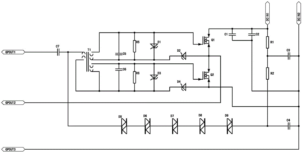
[0007] The present invention will be described in further detail below in conjunction with the accompanying drawings.

[0008] A high-frequency generator circuit of the present invention, as attached figure 1 As shown, it includes a trigger circuit and a self-excited oscillation circuit; the trigger circuit includes a capacitor C1, a capacitor C2, a capacitor C3, a capacitor C4, a resistor R1, a resistor R2, a diac D5, a diac D6, a diac D7 , bidirectional trigger diode D8 and bidirectional trigger diode D9; the self-excited oscillation circuit includes capacitor C5, capacitor C6, capacitor C7, resistor R3, resistor R4, coupling transformer T1, Zener diode D1, Zener diode D2, Zener diode D3, Zener diode D4, MOS transistor Q1 and MOS transistor Q2; the high frequency generator also includes two input terminals and three output terminals, which are respectively the first input terminal of the high frequency generator and the second input terminal of the high frequency generator ...


PUM


Abstract

The invention discloses a high frequency generator circuit. The high frequency generator circuit comprises a trigger circuit and a self-oscillation circuit, wherein the trigger circuit comprises a capacitor C1, a capacitor C2, a capacitor C3, a capacitor C4, a resistor R1, a resistor R2, a bidirectional trigger diode D5, a bidirectional trigger diode D6, a bidirectional trigger diode D7, a bidirectional trigger diode D8 and a bidirectional trigger diode D9; and the self-oscillation circuit comprises a capacitor C5, a capacitor C6, a capacitor C7, a resistor R3, a resistor R4, a coupling transformer T1, a voltage stabilization diode D1, a voltage stabilization diode D2, a voltage stabilization diode D3, a voltage stabilization diode D4, a metal oxide semiconductor (MOS) tube Q1 and a MOS tube Q2. The high frequency generator circuit has the advantages that a suppression effect is simultaneously played in common-mode interference and differential-mode interference in a power grid.

Description

technical field [0001] The invention relates to a high frequency generator circuit. Background technique [0002] In the existing high-frequency generator circuit, the controller is basically involved, which leads to high cost of the high-frequency generator circuit; secondly, the high-frequency generator circuit does not set related components to the MOS tubes appearing in the circuit. Protection, thus reducing the stability and service life of the high-frequency generator circuit to a certain extent. Contents of the invention [0003] The technical problem to be solved by the present invention is to provide a high-frequency generator circuit with high stability, long service life and low cost. [0004] In order to solve the above technical problems, the technical solution provided by the present invention is: a high-frequency generator circuit, which includes a trigger circuit and a self-excited oscillation circuit; it is characterized in that: the trigger circuit inclu...

Claims


Application Information

Patent Timeline
IPC IPC(8): H05B41/285
CPCY02B20/00
Inventor 王侃
Owner 王侃
Features
  • R&D
  • Intellectual Property
  • Life Sciences
  • Materials
  • Tech Scout
  • Unparalleled Data Quality
  • Higher Quality Content
  • 60% Fewer Hallucinations
Learn More