Split section staggered insertion type curtain track
A plug-in and track technology, which is applied in the field of curtain track, can solve the problems that the place where the connecting device is placed is difficult to bend, the difficulty of market promotion of the curtain track is increased, and the satisfaction of the user experience is reduced, so as to achieve smooth sliding and quietness, and save transportation time and cost, and the effect of reducing the transportation link
- Summary
- Abstract
- Description
- Claims
- Application Information
AI Technical Summary
Problems solved by technology
Method used
Image
Examples
Embodiment 1
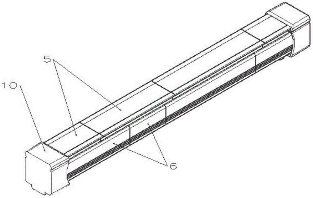
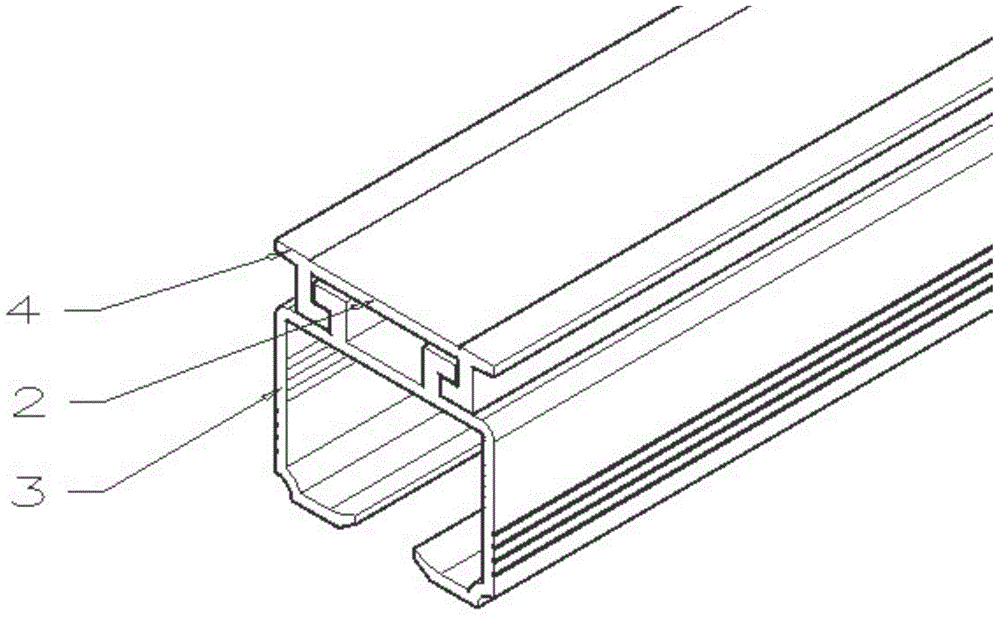
[0033] As shown in the figure, this embodiment first takes the straight rail as an example to introduce the split and segmented interlaced plug-in curtain track of the present invention.
[0034] A split and segmented staggered plug-in curtain track, comprising a track body 1, which is matched with the claw-type slot of the installation code, and fixed on the wall of the window. The track body 1 includes equal-length The upper claw buckle bar 2 and the lower track bar 3; the top two sides of the upper claw buckle bar 2 protrude to form a card edge 4 matching the claw type slot of the installation code, and the bottom of the upper claw buckle bar 2 The top of the lower track bar 3 forms an assembly mechanism that is longitudinally inserted and fixed up and down; the upper claw buckle bar 2 is formed by connecting at least two sections of claw button bodies 5 in sequence, and the lower track bar 3 is formed by at least two sections of track bodies 6 in turn. It is formed by conn...
Embodiment 2
[0050] As shown in the figure, this embodiment takes the I-shaped rail as an example to introduce the split, segmented, interlaced plug-in curtain track of the present invention.
[0051] The difference between this embodiment and embodiment 1 is:
[0052] The assembly mechanism is a slot 8 arranged longitudinally along the top of the lower track bar 3, and an insert block 7 arranged at the bottom of the upper claw buckle bar 2 and matched with the slot 8; in addition, as an I-shaped rail, The cross-section of the track main body 1 of this embodiment is I-shaped, and the cross-section of the slot 8 of the assembly mechanism is a circle with an arc top opening, and the shape of the insert block 7 corresponds to the slot 8; for the I-shaped rail, it is also A spacer 9 having the same length as the track main body 1 and wrapping on the bottom inner wall of the track main body 1 may be provided.
[0053] When setting the pulleys of the I-shaped rail, two pulleys are usually paire...
Embodiment 3
[0056] As shown in the figure, this embodiment takes the mantle rail as an example for an introduction.
[0057] As a mantle rail, one side of the lower rail bar of the track main body 1 is provided with a Velcro, and the curtain is pasted on the Velcro on this side.
[0058] This embodiment is not provided with gasket 9, track cover 10, pressing member 11, etc., and other technical features are the same as or corresponding to those of Embodiment 1 and Embodiment 2, and will not be repeated here.
[0059] Through the description of the foregoing embodiments, it can be seen that the present invention has the following advantages:
[0060] 1. The upper and lower parts of the shorter track are convenient for shipment and distribution, and the combination and installation are convenient, reducing transportation links, saving transportation time and cost, and are very suitable for online shopping express delivery;
[0061] 2. Aluminum alloy can be used as the main body of the trac...
PUM
 Abstract
Description
Claims
Application Information
 - R&D
- Intellectual Property
- Life Sciences
- Materials
- Tech Scout
- Unparalleled Data Quality
- Higher Quality Content
- 60% Fewer Hallucinations
Browse by: Latest US Patents, China's latest patents, Technical Efficacy Thesaurus, Application Domain, Technology Topic, Popular Technical Reports.
© 2025 PatSnap. All rights reserved.Legal|Privacy policy|Modern Slavery Act Transparency Statement|Sitemap|About US| Contact US: help@patsnap.com


