Carrier band forming device and method

A molding device and carrier tape technology, which is applied to belts, other household appliances, household appliances, etc., can solve the problems of inability to manufacture carrier tapes, increased manufacturing costs of carrier tapes, and impossibility, so as to save the manufacturing cost of carrier tapes and save manufacturing The effect of reducing cost and reducing processing difficulty

Active Publication Date: 2015-11-18
广东昭信平洲电子有限公司
View PDF3 Cites 0 Cited by
  • Summary
  • Abstract
  • Description
  • Claims
  • Application Information

AI Technical Summary

Problems solved by technology

In the die stamping method, the cavity wall of the carrier tape is mainly formed by stretching and deforming a small area of ​​material; the cavity wall of a deep cavity needs to be greatly stretched on a small area of ​​material, which may easily cause the cavity wall to be too thin , or even breakage; if the width of the middle wall is designed to be small at this time, it is necessary to realize the stretching of two adjacent cavity walls on a small area of ​​material, so the die stamping method is even less likely to be applied to narrow Carrier tape manufacturing occasions for deep cavities in the middle wall
However, when the blow molding method is applied to the manufacture of carrier tapes with narrow walls and deep cavities, the blow molding equipment needs to adjust multiple parameters such as blow intensity and blow delay time, and it is difficult to obtain a good forming effect. Medium load belt is prone to deformation
Therefore, the existing two carrier tape manufacturing methods cannot produce a carrier tape with a narrow middle wall and a deep cavity; at present, manufacturers often meet the cavity depth requirements by widening the size of the sheet and widening the size of the middle wall
However, this approach increases the manufacturing cost of the carrier tape by at least 60%, which is not conducive to enterprises to seize the carrier tape market

Method used


Image

  • Carrier band forming device and method
  • Carrier band forming device and method
  • Carrier band forming device and method

Examples


Embodiment 1

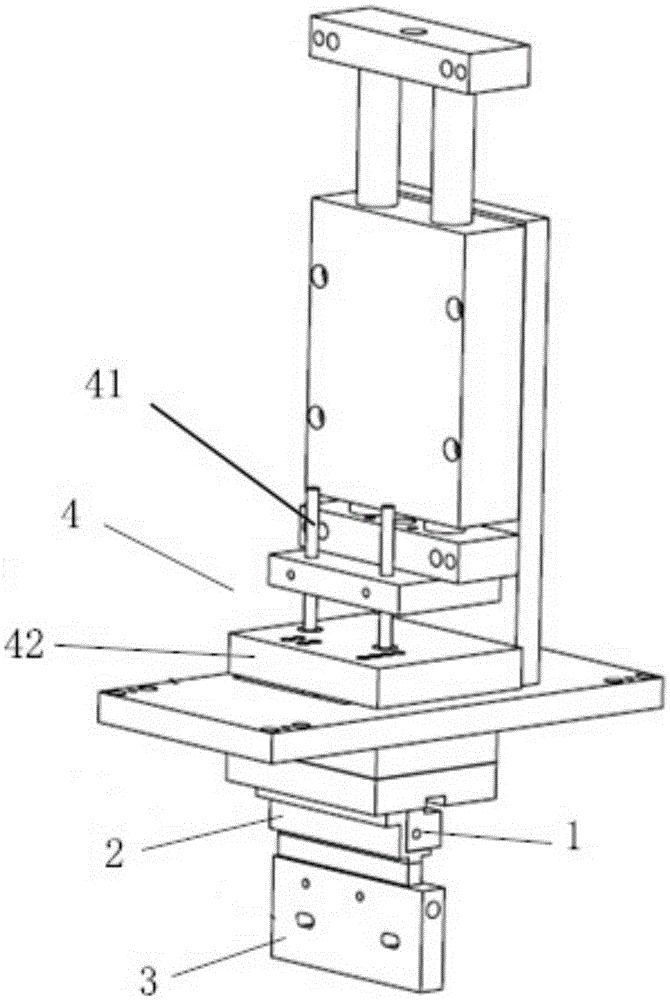
[0042] This embodiment describes a carrier tape forming device for making a sheet into a carrier tape; its structure is as follows figure 1 Shown; including frame and gas input unit, as well as molding upper mold 1, molding lower mold 3 and clamping unit 2.

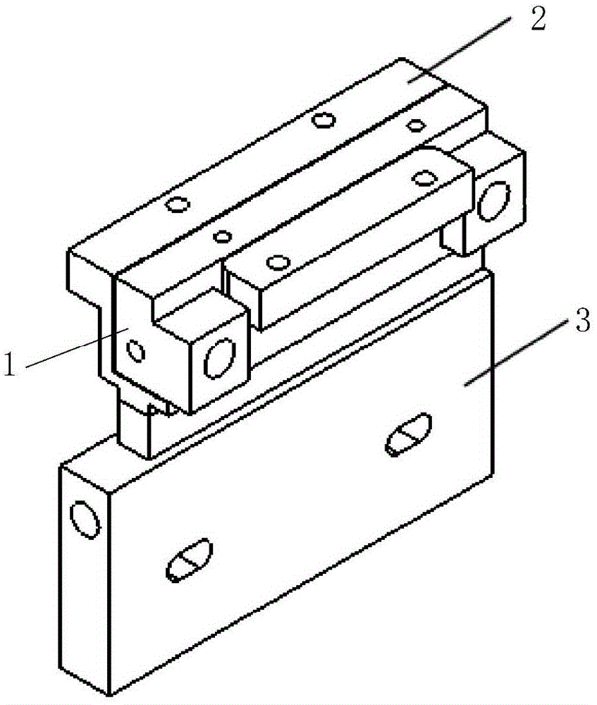
[0043] Wherein, forming lower mold 3 is positioned at the lower side of clamping unit 2, as figure 2 As shown; the clamping unit 2 is connected to the frame; the forming lower mold 3 is connected to the frame through the lower mold driving unit to realize that the forming lower mold 3 moves toward the clamping unit 2 and moves away from the clamping unit 2, thereby realizing the clamping unit 2 and the distance between the forming lower die 3 is adjusted. The clamping unit 2 and the lower forming die 3 are used to clamp the sheet, and the positioning of the sheet can be realized by adjusting the distance between the clamping unit 2 and the lower forming die 3 .

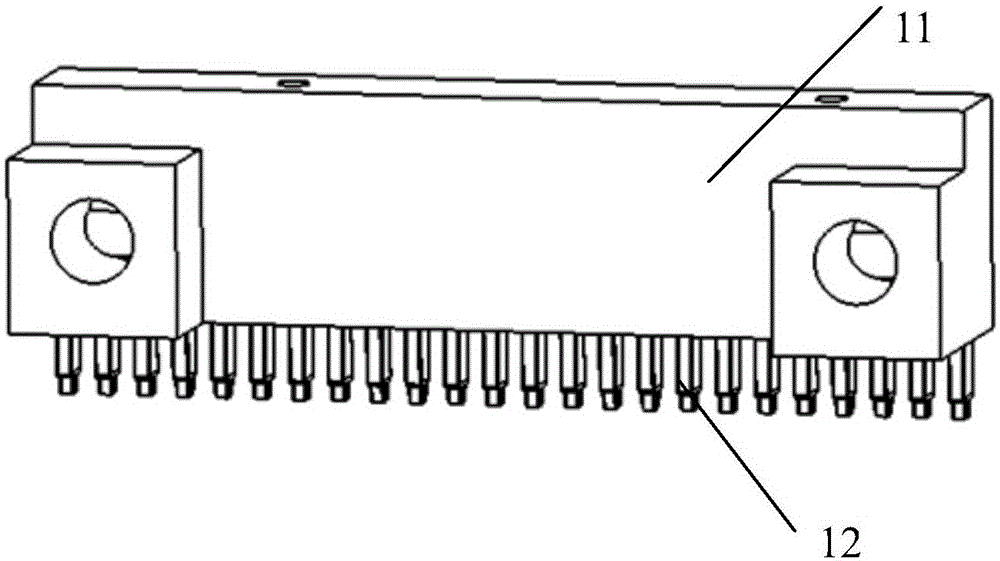
[0044] Such as image 3 As shown, the forming upper mol...

Embodiment 2

[0055] The difference between the carrier tape forming device of this embodiment and Embodiment 1 is that: in the carrier tape forming device of this embodiment, the forming lower mold is connected to the frame; the clamping unit is connected to the frame through the clamping drive unit to move the clamping unit to Realize the adjustment of the distance between the clamping unit and the forming lower mold. The rest of the structure of this embodiment is the same as that of Embodiment 1.

Embodiment 3

[0057] This embodiment describes a carrier tape forming method, which is used to make a sheet into a carrier tape, and its working process is as follows Figure 7 shown; includes the following steps:

[0058] In the first step, the sheet is placed on the side of the forming lower die with the lower die hole, and the clamping unit is used to clamp the sheet together with the forming lower die;

[0059] In the second step, the forming upper mold moves toward the forming lower mold until the forming cylinder with the forming upper mold enters the lower mold hole opened by the forming lower mold, and the sheet is positioned at the lower mold hole during the forming cylinder enters the lower mold hole. The part of the die hole is pressed into the lower die hole by the forming cylinder to form the initial cavity; since the gap between the forming cylinder and the lower die hole is greater than the thickness of the sheet, the initial cavity is respectively connected to the forming cy...


PUM


Abstract

The invention provides a carrier band forming device. The carrier band forming device comprises a rack, a gas input unit, an upper forming die, a lower forming die and a clamping unit, wherein the upper forming die, the lower forming die and the clamping unit are connected with the rack. The clamping unit is opposite to the lower forming die in position. The distance between the clamping unit and the lower forming die can be adjusted. The upper forming die comprises an upper die base body and a plurality of forming cylinders. The lower forming die is provided with a plurality of lower die holes corresponding to the forming cylinders in position. The upper die base body is connected with the rack through an upper die driving unit. Gaps are reserved between all the forming cylinders and the hole walls of the lower die holes. The gas input unit is connected with the lower forming die so that compressed gas can be input. By the adoption of the carrier band forming device, product quality can be improved, carrier band deformation is avoided, narrow center wall deep cavity carrier bands can be manufactured, and the manufacturing cost of the carrier bands is reduced. The invention further provides a carrier band forming method capable of lowering machining difficulty of the carrier bands, improving machining efficiency, avoiding carrier band deformation and achieving manufacturing of the narrow center wall deep cavity carrier bands.

Description

technical field [0001] The invention relates to the technical field of carrier tape forming, and more specifically, to a carrier tape forming device and method. Background technique [0002] Carrier tape is a strip-shaped product used in the field of electronic packaging. Cavities for holding electronic components are distributed equidistantly along its length; a middle wall is formed between adjacent cavities for electronic components. Quarantine. At present, the manufacturing methods of carrier tape generally include die stamping method and blow molding method. The die stamping method refers to the use of upper and lower dies to directly press the sheet into the required shape of the carrier tape. The blow molding method refers to placing the sheet on the mold, and setting an air cover above the sheet to form a sealed space, and blowing compressed air into the sealed space to make the sheet fit the mold and form it. [0003] With the development of science and technolog...

Claims


Application Information

Patent Timeline
IPC IPC(8): B29C51/18B29C51/30B29C51/10B29L29/00
Inventor 廖镜堂叶昱明袁跃宏何毅刚董书亮
Owner 广东昭信平洲电子有限公司
Why Eureka
Try Eureka