
Method for retraining vibration of rotary shaft system

A technology for rotating shafts and bearings, applied in the field of vibration suppression, can solve the problems of harsh requirements of driving components, difference in vibration amplitude of shafting, inability to eliminate resonance, etc., and achieve the effect of simple structure, vibration suppression, and good vibration suppression effect.

Inactive Publication Date: 2015-11-18
HARBIN INST OF TECH
View PDF6 Cites 5 Cited by
  • Summary
  • Abstract
  • Description
  • Claims
  • Application Information

AI Technical Summary

Problems solved by technology

[0006] The purpose of the present invention is to solve the problems that existing vibration suppression methods for the rotating shaft system to quickly traverse the resonance frequency cannot eliminate the resonance, the requirements for the drive components are harsh, and the vibration amplitudes of the shaft system are different at different operating speeds. The present invention provides a The Method of Suppressing the Vibration of the Rotating Shaft System

Method used


Image

  • Method for retraining vibration of rotary shaft system
  • Method for retraining vibration of rotary shaft system

Examples


specific Embodiment approach 1

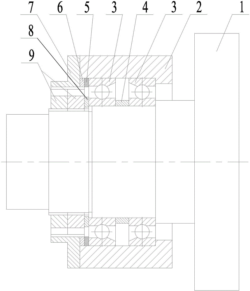
[0018] Specific implementation mode one: see figure 1 Describe this embodiment, a method for suppressing the vibration of the rotating shaft system described in this embodiment, the method is realized based on the rotating shaft system, and the rotating shaft system includes a rotating shaft 1, a base 2, and two bearings 3 , middle spacer 4, outer ring preload gasket 6, end cap 7, inner ring preload gasket 8 and two preload nuts 9; the specific process of the method is:

[0019] Step A1: Add a piezoelectric adjustment ring 5 in the rotating shaft system,

[0020] The rotating shaft 1 is rotationally connected with the base 2 through two bearings 3;

[0021] The middle spacer 4 is arranged between the two bearings 3, and the two sides of the middle spacer 4 are respectively in contact with the inner rings of the two bearings 3; the outer ring of the right bearing 3 is in contact with the shaft shoulder on the base 2, and the right The inner ring of the side bearing 3 is in co...

specific Embodiment approach 2

[0028] Specific implementation mode two: see figure 1 This embodiment is described. The difference between this embodiment and the method for suppressing the vibration of the rotating shaft system described in the first embodiment is that the intermediate spacer 4 is a piezoelectric adjustment ring.

specific Embodiment approach 3

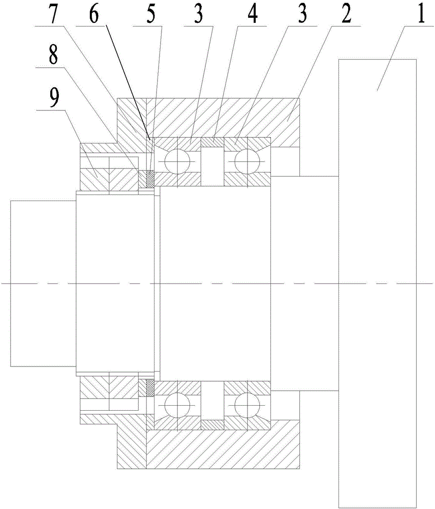
[0029] Specific implementation mode three: see figure 2 Describe this embodiment, a method for suppressing the vibration of the rotating shaft system described in this embodiment, the method is realized based on the rotating shaft system, and the rotating shaft system includes a rotating shaft 1, a base 2, and two bearings 3 , middle spacer 4, outer ring preload gasket 6, end cap 7, inner ring preload gasket 8 and two preload nuts 9; the specific process of the method is:

[0030] Step A1: Add a piezoelectric adjustment ring 5 in the rotating shaft system,

[0031] The rotating shaft 1 is rotationally connected with the base 2 through two bearings 3;

[0032] The middle spacer 4 is arranged between the two bearings 3, and the two sides of the middle spacer 4 are respectively in contact with the outer rings of the two bearings 3, the outer ring of the right bearing 3 is in contact with the shaft shoulder on the base 2, and the right The inner ring of the side bearing 3 is in...


PUM


Abstract

The invention provides a method for retraining vibration of a rotary shaft system and belongs to the technical field of vibration restraint. The problems that an existing method for restraining vibration generated when a rotary shaft system quickly passes through resonant frequency cannot eliminate resonance and is strict for requirements for a drive element, and the vibration ranges of the shaft system at different working rotating speeds differ are solved through the method. According to the method, a piezoelectric adjusting ring is arranged on the side faces of the inner rings or the outer rings of bearings in the rotary shaft system, when the rotating speed of the rotary shaft system is close to certain resonant frequency of the rotary shaft system, direct current excitation signals are applied to the piezoelectric adjusting ring, and the thickness of the piezoelectric adjusting ring is increased under the inverse piezoelectric effect, so that the pre-tightening force of the bearings is increased, the supporting rigidity of the bearings is correspondingly increased, and finally the resonant frequency of the rotary shaft system is increased; when the rotating speed of the rotary shaft system stably exceeds the original resonant frequency, the piezoelectric adjusting ring is powered off, the resonant frequency of the rotary shaft system is changed into the original resonant frequency, and therefore resonance is avoided. The method is applied to the field of vibration restraint.

Description

technical field [0001] The invention belongs to the technical field of vibration suppression. Background technique [0002] Vibration problems are inevitable in the working process of various mechanical equipment, and vibration will affect the machining accuracy of machine tools, the working accuracy of robots, the trajectory accuracy of aircraft, etc.; therefore, vibration suppression has always been an issue in the field of mechanical engineering. Core and key technologies. Among the vibration suppression of various mechanisms, the vibration suppression of the rotating shaft system is the most concerned issue for those in the engineering field. For example, the vibration of the spindle of a precision machining machine tool will directly affect its machining accuracy. [0003] The vibration suppression problem of the rotating shaft system is relatively complicated. The core problem is that the number of its natural vibration modes is infinite, and when the rotating speed ...

Claims


Application Information

Patent Timeline
Patent Type & Authority Applications(China)
IPC IPC(8): F16F15/10
CPCF16F15/18
Inventor 刘英想陈维山刘军考冯培连
Owner HARBIN INST OF TECH
Learn More