A kind of sintering ignition control method of sintering machine

A technology of ignition control and sintering machine, applied in the direction of furnace type, furnace, lighting and heating equipment, etc., can solve the problems of ignition heat loss on material surface, uneven distribution of sintering wind, insufficient ignition heat supply, etc., to reduce ignition fuel and Effect of air flow, optimization of sinter quality, improvement of ignition effect

Active Publication Date: 2017-05-31
TIANJIN TIANGANG UNITED SPECIAL STEEL CO LTD
View PDF8 Cites 0 Cited by
  • Summary
  • Abstract
  • Description
  • Claims
  • Application Information

AI Technical Summary

Problems solved by technology

Due to the edge effect, on the one hand, it is difficult to ignite the carbon on the surface of the material layer on both sides of the sintering machine trolley, and on the other hand, it also causes a serious loss of ignition heat on the material surface on both sides of the sintering machine, so that when the trolley moves past the burner, it burns Two situations may occur: when the sintered material in the central area of ​​the sintering machine meets the normal ignition and heat supply requirements, the sintered material on both sides of the sintering machine may have insufficient ignition and heat supply, resulting in the ignition of the solid fuel on both sides of the sintering machine Incomplete, even the solid fuel has not been ignited, resulting in poor quality of sintered ore on both sides; and when the sintered material in the edge area of ​​the sintering machine meets the normal ignition heating demand, the heat supply in the middle area of ​​the sintering machine will be excessive, so The sintering material in the middle area will be over-melted, which will affect the air permeability of the material layer in the central area, and then lead to the uneven distribution of sintering air, which will eventually affect the quality of sintered minerals and energy consumption

Method used


Image

  • A kind of sintering ignition control method of sintering machine
  • A kind of sintering ignition control method of sintering machine
  • A kind of sintering ignition control method of sintering machine

Examples


Embodiment Construction

[0018] In order to further understand the invention content, characteristics and effects of the present invention, the following examples are given, and detailed descriptions are as follows in conjunction with the accompanying drawings:

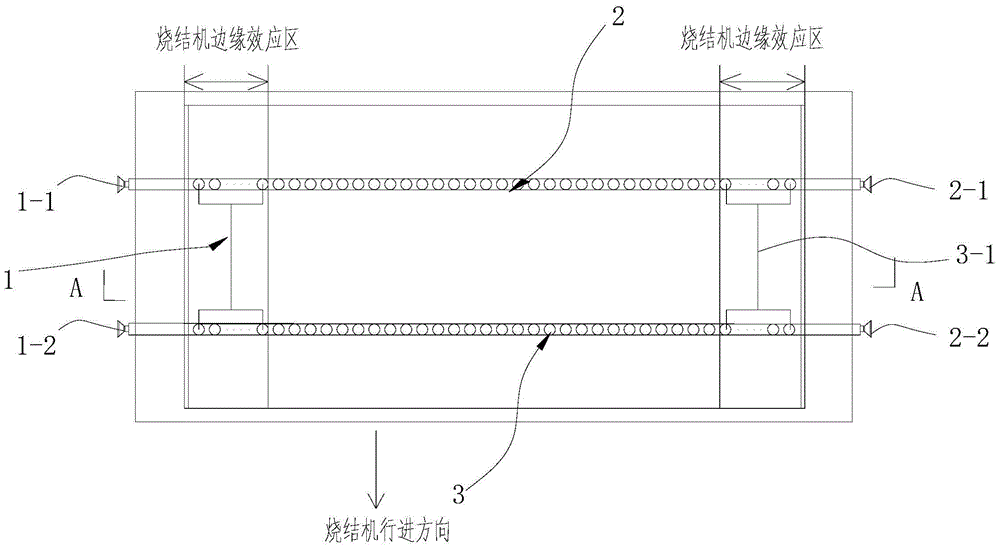
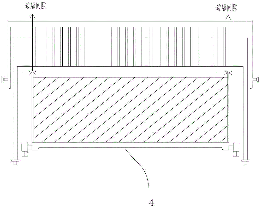
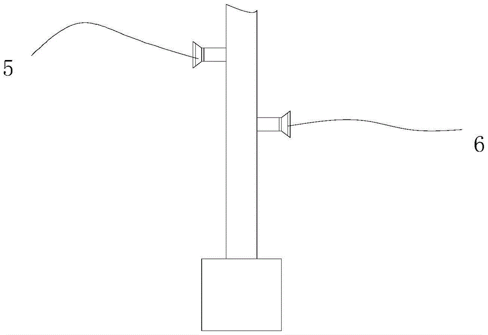
[0019] see Figure 1 to Figure 3 , a sintering ignition control method for a sintering machine, the sintering machine is arranged with several rows of ignition burners, such as the first row of ignition burners 2, the second row of ignition burners 3, etc., and the edge area of ​​the sintering machine is arranged with several rows of edge points Fire burner 3-1, such as the first row of edge ignition burners, the second row of edge ignition burners, etc., the igniter is arranged with several ignition fuel and air flow regulating valves, such as ignition fuel flow regulating valve 1-1 , ignition fuel flow regulating valve 1-2, ignition air flow regulating valve 2-1, ignition air flow regulating valve 2-2, ignition burner fuel flow regulating v...


PUM


Abstract

The invention relates to a sintering ignition control method of a sintering machine. The method is characterized in that based on ignition fuel and airflow that are the same as those in Step 1, an adding proportion of the ignition fuel to air of ignition burners in the first row of the sintering machine is increased, and the increased adding proportion is 1.1-1.5 times of the original adding ratio; in addition, adding proportions of the ignition fuel to the air of the ignition burners in other rows of the sintering machine are reduced sequentially, and each reduced adding ratio is 0.4-0.9 times of the reduced adding ratio of the previous row; based on the ignition fuel and the airflow in Step 2, adding ratios of the ignition fuel to the air of the various ignition burners at the edges of the sintering machine are increased, and the increased adding ratios are reduced gradually from the edges of the sintering machine to a middle area and are 1.2-2.0 times of the original adding ratios correspondingly; and the best adding ratios of the ignition fuel to the air of the ignition burners in the first row and the other rows of and the ignition burners at the edges of the sintering machine are selected according to comparison on various parameters. With the adoption of the method, the ignition effect is improved; the ignition quality of a sintering material at the edges of the sintering machine, and distribution of sintering air on the surface of the sintering material are improved, and the quality of sintering mineral products are optimized.

Description

technical field [0001] The invention belongs to the technical field of sintering machine ignition control, in particular to a sintering machine sintering ignition control method. Background technique [0002] At present, most of the sintering machine ignition devices used in the sintering plant are igniters with multiple rows (two rows, three rows, four rows) of burners, and the ignition fuel and air flow of the ignition burners in each row of the igniter are the same, that is, each row The ignition intensity of the sintered materials is the same. The first row of ignition burners are ignited to ignite the solid fuel in the material, and then the air is sucked in by the suction of the ventilation system, and the solid fuel is burned, so that the sintering process can be carried out downwards, that is, the first row of ignition burners play a role The function is to ignite. The purpose of igniting the other rows of ignition burners is: a. For some reason, the first row of i...

Claims


Application Information

Patent Timeline
Patent Type & Authority Patents(China)
IPC IPC(8): F27B21/14
Inventor 呼建军崔金丽李宏飞
Owner TIANJIN TIANGANG UNITED SPECIAL STEEL CO LTD
Why Eureka
Try Eureka