A pre-ignition pulse burner

A pulsating combustion and pre-combustion technology, used in gas fuel burners, burners, combustion methods, etc., can solve the problems of uneven temperature distribution, high nitrogen oxide emissions, insufficient combustion, etc., to overcome uneven temperature distribution. , The effect of small exhaust heat loss and sufficient combustion

Inactive Publication Date: 2015-12-09
UNIV OF SCI & TECH OF CHINA
View PDF5 Cites 1 Cited by
  • Summary
  • Abstract
  • Description
  • Claims
  • Application Information

AI Technical Summary

Problems solved by technology

[0005] The technical problem to be solved by the present invention is: to overcome the deficiencies of the prior art, to provide a pre-combustion pulsation burner, to solve the current prior art of uneven temperature distribution in the combustion chamber, high emission of nitrogen oxides, insufficient combustion, The problem of low combustion efficiency

Method used


Image

  • A pre-ignition pulse burner
  • A pre-ignition pulse burner
  • A pre-ignition pulse burner

Examples


Embodiment 1

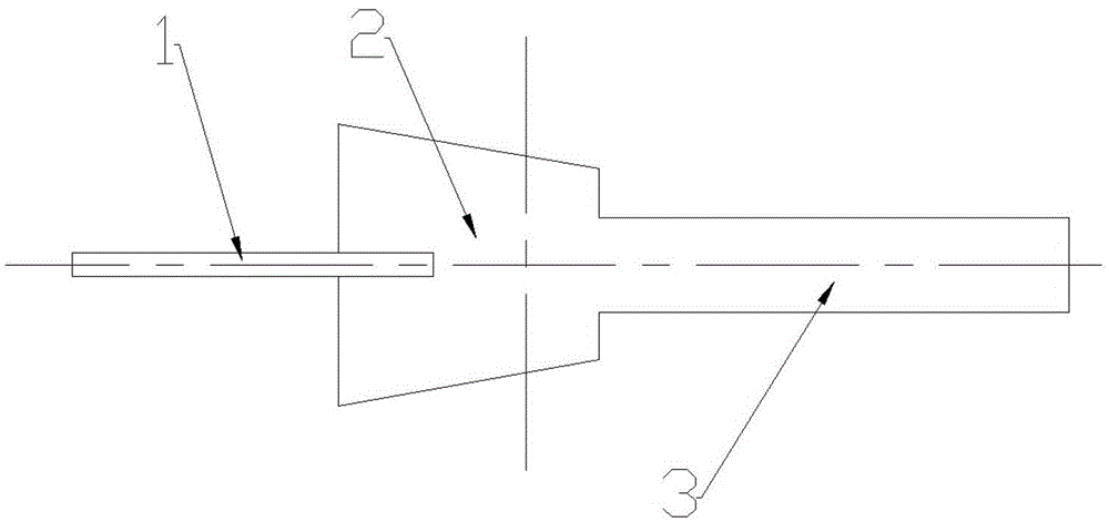
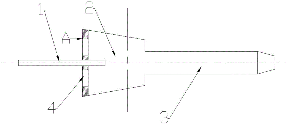
[0029] In this embodiment, it is composed of nozzle 1, pre-chamber 2 and tailpipe 3; pre-chamber 2 is a conical body, and the front end of pre-chamber 2 washes out 8 grooves 4 with b=0° (see figure 2 , 8, 9); b represents the inclination angle of the groove 4, when b=0°, the groove 4 is a straight groove; the nozzle 1 penetrates directly into the pre-chamber 2; The ends are connected, and the end of the tailpipe 3 is directly connected to the furnace.

[0030] The working principle of this embodiment is as follows (the fuel used in the implementation of this embodiment is solid or gaseous fuel):

[0031] In the initial stage, the fuel supply device passes N 2 The fuel is sprayed into the pre-chamber 2 through the nozzle 1, and at the same time, due to the turbulent diffusion of the jet, the entrained hot air enters the pre-chamber 2 through the groove 4, and the two interact in the pre-chamber 2. Mixing, because the temperature of the hot air is enough to reach the ignition...

Embodiment 2

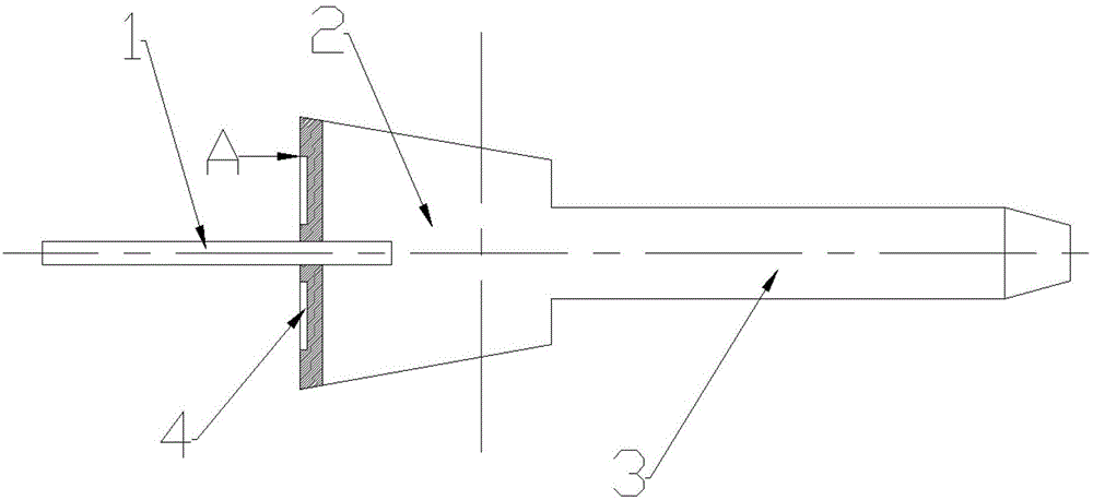
[0033] In this embodiment, it is composed of nozzle 1, pre-chamber 2 and tailpipe 3; pre-chamber 2 is a conical body, and the front end of pre-chamber 2 washes out 8 grooves 4 with b=30° (see image 3 , 8, 10, 11), the slots 4 are evenly distributed in right-handed or left-handed directions; the nozzle 1 penetrates directly into the pre-chamber 2; the front end of the tail pipe 3 is connected into the hearth.

[0034] The working principle of this embodiment is as follows (the fuel used in the implementation of this embodiment is solid or gaseous fuel):

[0035] In the initial stage, the fuel supply device passes N 2The fuel is sprayed into the pre-chamber 2 through the nozzle 1, and at the same time, due to the turbulent diffusion of the jet, the entrained hot air enters the pre-chamber 2 through the groove 4, and the two interact in the pre-chamber 2. Mixing, because the temperature of the hot air is enough to reach the ignition point of the fuel, so that the two can be mi...

Embodiment 3

[0037] In this embodiment, it is composed of nozzle 1, pre-chamber 2 and tailpipe 3; pre-chamber 2 is a conical body, and the front end of pre-chamber 2 washes out 8 grooves 4 with b=70° (refer to b=30° ), the grooves 4 are evenly distributed right-handed or left-handed; the nozzle 1 penetrates directly into the pre-combustion chamber 2; the front end of the tail pipe 3 is connected to the rear end of the pre-chamber 2, and the end of the tail pipe 3 is directly connected to the furnace.

[0038] The working principle of this embodiment is as follows (the fuel used in the implementation of this embodiment is solid or gaseous fuel):

[0039] In the initial stage, the fuel supply device passes N 2 The fuel is sprayed into the pre-chamber 2 through the nozzle 1, and at the same time, due to the turbulent diffusion of the jet, the entrained hot air enters the pre-chamber 2 through the groove 4, and the two interact in the pre-chamber 2. Mixing, because the temperature of the hot ...


PUM


Abstract

The invention provides a pre-burning type pulsating burner which comprises a nozzle, a pre-burning chamber and a tail pipe. Grooves with b equal to 0 degree to 70 degrees are washed at the front end of the pre-burning chamber and are evenly distributed in a right-handed rotation or left-handed rotation mode, air entering is guaranteed, rotational flow effect is achieved, and the rear end of the pre-burning chamber is connected with the tail pipe so as to discharge burning products. Fuel enters the pre-burning chamber through the nozzle to be mixed with air. Due to the fact that air flow pulsation and the burning process have coupling effect, the pulsating burner can perform self-absorption of air and the fuel from the position of an inlet and gas is discharged towards an outlet at a certain pressure. Due to the fact that a pulsation technology is adopted to enable hot air and the fuel to be absorbed into the pre-burning chamber under pressure changes of the pre-burning chamber, the burning products are sprayed into a hearth through the tail pipe so as to be burned in a flameless mode within a large area simultaneously, an excess air coefficient is reduced, and burning efficiency is improved.

Description

technical field [0001] The invention relates to a pre-combustion type pulsating burner, which belongs to the technical field of combustion equipment boilers. Background technique [0002] The fuel combustion of traditional burners is insufficient, the combustion rate is slow, and the thermal efficiency is low, which seriously causes waste of energy, and NO x Emissions are relatively high, and my country's demand for energy continues to grow, so energy and environmental issues have become more prominent at this time. [0003] Pulsating combustion is a combustion in which the flow parameters of fuel and oxygen (air) fluctuate periodically during the combustion process. This technology is a new type of combustion technology with high efficiency, energy saving, cleanliness and environmental protection. It can not only achieve high combustion efficiency in a low excess air coefficient and limited combustion space, but also has extremely high combustion intensity, thermal efficie...

Claims


Application Information

Patent Timeline
Patent Type & Authority Patents(China)
IPC IPC(8): F23D14/10F23D14/46
Inventor 林其钊杨亚军
Owner UNIV OF SCI & TECH OF CHINA
Why Eureka
Try Eureka