A kind of injection pre-combustion flameless burner

A flameless combustion and pre-combustion chamber technology, applied in the direction of gas fuel burners, burners, burners burning powder fuel, etc., can solve problems such as uneven temperature distribution, high nitrogen oxide emissions, and insufficient combustion. Achieve the effects of overcoming uneven temperature distribution, improving combustion efficiency, and speeding up the reaction

Inactive Publication Date: 2015-09-09
UNIV OF SCI & TECH OF CHINA
View PDF8 Cites 0 Cited by
  • Summary
  • Abstract
  • Description
  • Claims
  • Application Information

AI Technical Summary

Problems solved by technology

[0006] The technical problem of the present invention is to overcome the deficiencies of the prior art, and provide an injection pre-combustion flameless burner, which solves the problems of uneven temperature distribution in the combustion chamber, high nitrogen oxide emissions, insufficient combustion, The problem of low combustion efficiency

Method used


Image

  • A kind of injection pre-combustion flameless burner
  • A kind of injection pre-combustion flameless burner
  • A kind of injection pre-combustion flameless burner

Examples


Embodiment 1

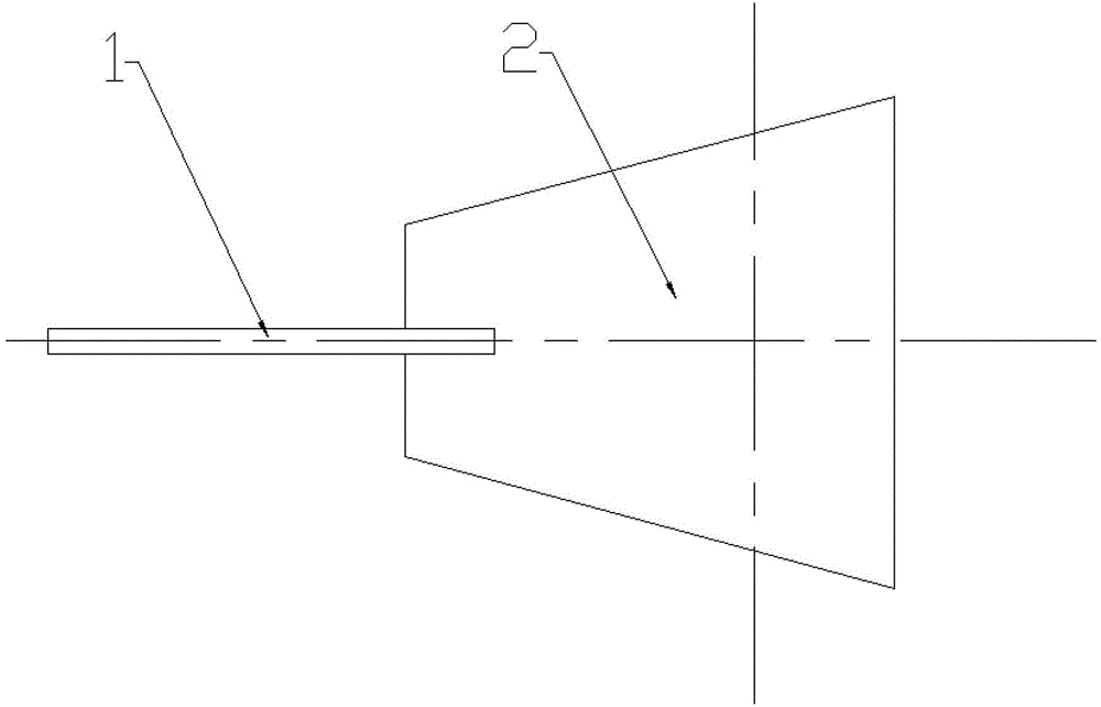
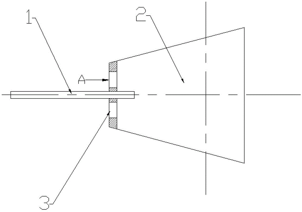
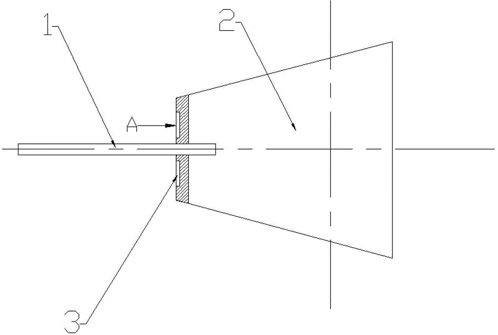
[0023] In this embodiment, it consists of a nozzle 1 and a pre-chamber 2; the front end of the pre-chamber 2 washes out 8 grooves 3 with b=0° (see figure 2 , 4, 5, that is, the groove 3 is a straight groove); the nozzle 1 goes directly into the pre-combustion chamber 2; the end of the pre-combustion chamber 2 is directly connected to the furnace.

[0024] The working principle of the embodiment of the present invention is as follows (the fuel used in the implementation of the embodiment of the present invention is solid or gaseous fuel):

[0025] In the initial stage, the fuel supply device passes N 2 The fuel is sprayed into the pre-chamber 2 through the nozzle 1. At the same time, due to the turbulent diffusion of the jet, the entrained hot air enters into the pre-chamber 2 through the groove 3, and the two interact in the pre-chamber 2. Mixing, because the temperature of the hot air is enough to reach the ignition point of the fuel, so that the two can be mixed and burned...

Embodiment 2

[0027] In this embodiment, it consists of a nozzle 1 and a pre-chamber 2; the front end of the pre-chamber 2 washes out 8 grooves 3 with b=30° (see image 3 , 4, 6, 7, that is, the groove 3 is a chute), the groove 3 is evenly distributed in the right or left direction; the nozzle 1 goes directly into the pre-combustion chamber 2; the end of the pre-combustion chamber 2 is directly connected to the furnace.

[0028] The working principle of the embodiment of the present invention is as follows (the fuel used in the implementation of the embodiment of the present invention is solid or gaseous fuel):

[0029] In the initial stage, the fuel supply device passes N 2 The fuel is sprayed into the pre-chamber 2 through the nozzle 1. At the same time, due to the turbulent diffusion of the jet, the entrained hot air enters into the pre-chamber 2 through the groove 3, and the two interact in the pre-chamber 2. Mixing, because the temperature of the hot air is enough to reach the ignitio...

Embodiment 3

[0031] In this embodiment, it consists of a nozzle 1 and a pre-chamber 2; the front end of the pre-chamber 2 washes out 8 grooves 3 with b=70° (refer to b=30°, that is, the groove 3 is still a chute), and the groove 3 Right-handed or left-handed evenly distributed; Nozzle 1 goes deep into the pre-chamber 2; The end of the pre-chamber 2 is directly connected to the furnace.

[0032] The working principle of the embodiment of the present invention is as follows (the fuel used in the implementation of the embodiment of the present invention is solid or gaseous fuel):

[0033] In the initial stage, the fuel supply device passes N 2 The fuel is sprayed into the pre-chamber 2 through the nozzle 1. At the same time, due to the turbulent diffusion of the jet, the entrained hot air enters into the pre-chamber 2 through the groove 3, and the two interact in the pre-chamber 2. Mixing, because the temperature of the hot air is enough to reach the ignition point of the fuel, so that the t...


PUM


Abstract

The invention provides an ejecting pre-burning type flameless burner, which comprises a spray nozzle and a pre-burning chamber, wherein grooves at inclination angles b of 0 DEG to 70 DEG, which are milled at the front end of the pre-burning chamber, are evenly distributed in a rightward rotating or leftward rotating manner, so as to guarantee that air enters the pre-burning chamber and achieves a rotational flow effect; and the back end of the pre-burning chamber is directly connected with a furnace hearth, so as to discharge burning products. Fuel enters the pre-burning chamber through the spray nozzle to be mixed with air; and through adopting an ejecting technology, the air is sucked into the pre-burning chamber via the grooves, and flameless burning can be realized by using gas and solid fuel. The ejecting pre-burning type flameless burner has the advantages that as the ejecting method is adopted, the hot air is ejected into the pre-burning chamber under the jet action of the fuel, and the burning products are finally sprayed into the furnace hearth to be burned in a flameless manner in a relatively large area, so that the excess air coefficient is reduced, the burning efficiency is improved and the burning noise is reduced.

Description

technical field [0001] The invention relates to an injection pre-combustion flameless burner, which belongs to the technical field of combustion equipment boilers. Background technique [0002] The fuel combustion of traditional burners is insufficient, the combustion rate is slow, and the thermal efficiency is low, which seriously causes waste of energy, and NO x Emissions are relatively high, and my country's demand for energy continues to grow, so energy and environmental issues have become [0003] more prominent. [0004] The ejector is a fluid machine and a mixing reaction device that uses the turbulent diffusion of the jet to mix two fluids of different pressures and cause energy exchange. The ejector is mainly composed of working nozzles, receiving chambers, mixing chambers and diffusion chambers. Before entering the device, the fluid with higher pressure is called the working fluid. It flows out from the nozzle at a high speed and enters the receiving chamber. Du...

Claims


Application Information

Patent Timeline
Patent Type & Authority Patents(China)
IPC IPC(8): F23D1/00F23D14/04
Inventor 林其钊杨亚军杨必应
Owner UNIV OF SCI & TECH OF CHINA
Why Eureka
Try Eureka