
A kind of pre-combustion type plasma igniter and ignition method

A plasma and igniter technology, applied in the direction of machines/engines, gas turbine devices, turbine/propellant fuel delivery systems, etc., can solve problems such as difficult to achieve high-altitude secondary ignition, unable to meet the needs of aircraft, and reduced chemical reaction rates, etc., to achieve Easy assembly, easy industrial production and processing, and the effect of promoting combustion reaction

Active Publication Date: 2019-07-23
XI AN JIAOTONG UNIV
View PDF4 Cites 1 Cited by
  • Summary
  • Abstract
  • Description
  • Claims
  • Application Information

AI Technical Summary

Problems solved by technology

The physical and chemical properties of fuel oil in the high-altitude low-temperature and low-pressure environment are significantly different from those in the normal temperature and pressure environment, resulting in a significant decrease in the chemical reaction rate, a significant decrease in the flame propagation speed, and difficulty in ignition, which in turn makes it difficult to achieve high-altitude secondary ignition
[0003] The ignition height of existing aero-engine igniters is 8-9km, and it can reach 12-13km after oxygen supplementation and other measures are taken. For high-altitude aircraft, this ignition height still cannot meet the needs of aircraft

Method used


Image

  • A kind of pre-combustion type plasma igniter and ignition method
  • A kind of pre-combustion type plasma igniter and ignition method
  • A kind of pre-combustion type plasma igniter and ignition method

Examples


Embodiment Construction

[0037] The present invention will be further described now in conjunction with accompanying drawing.

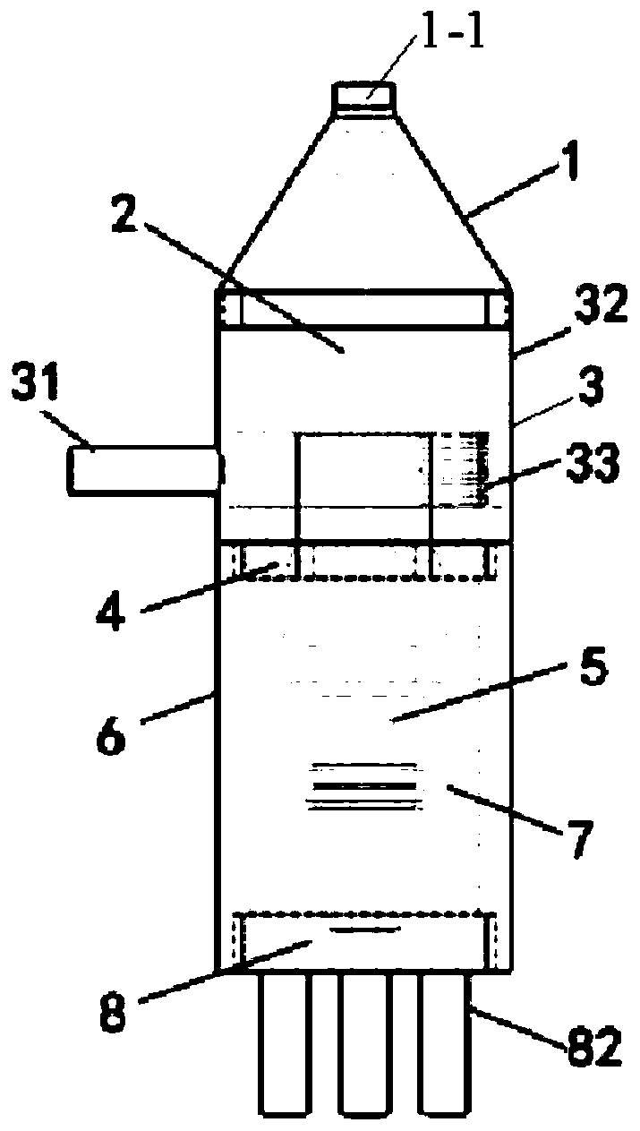
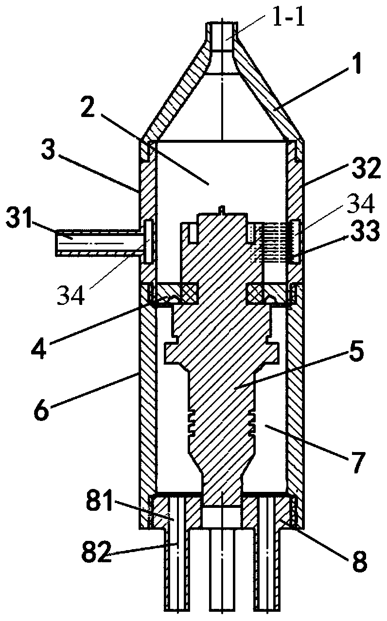
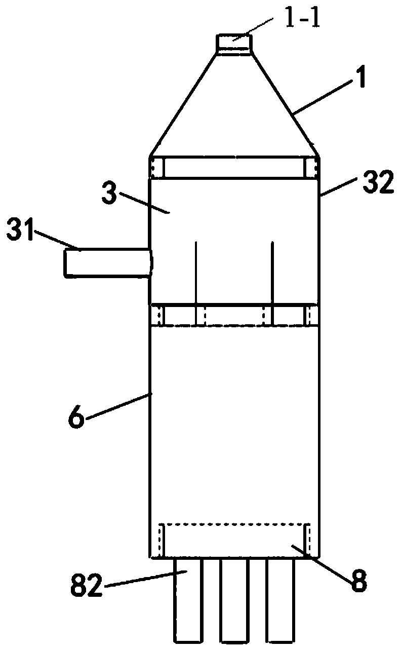
[0038] Such as Figure 1 to Figure 12 As shown, the pre-combustion plasma igniter of the present invention includes a nozzle 1, a pre-combustion chamber 2, a thin-walled fuel tube 3, a swirler 4, a spark plug 5, a sleeve 6, a rectifying chamber 7 and an air passage 8 base. The interior of the pre-combustion plasma igniter is a cavity structure, which is divided into upper and lower parts by the cyclone 4: the upper part is the pre-combustion chamber 2, and the lower part is the rectifying chamber 7. The part corresponding to the pre-combustion chamber 2 is composed of the thin-walled fuel pipe 3 and the nozzle 1. The fuel flows into the annular cavity oil delivery chamber 34 opened in the thin-walled fuel pipe 3 through the oil delivery pipe 31, and is atomized under the action of pressure. The hole 33 is ejected to the pre-combustion chamber 2; the corresponding part of the...


PUM


Abstract

The invention discloses a pre-combustion type plasma igniter and an ignition method. The pre-combustion type plasma igniter comprises a shell, an oil conveying pipe, a hydrocyclone, a spark plug and agas channel base. A jetting opening is formed in the upper end of the shell. The hydrocyclone is arranged in the shell and connected with the shell. The hydrocyclone divides an inner cavity of the shell into a pre-combustion chamber and a rectification chamber. The spark plug is arranged on the inner cavity of the shell, penetrates the hydrocyclone and is connected with the hydrocyclone, and thehigh-voltage electrode of the spark plug is located in the pre-combustion chamber. An oil conveying cavity is formed in the shell wall of the portion, corresponding to the pre-combustion chamber, of the shell. The oil conveying pipe communicates with the oil conveying cavity. An atomizing hole is formed in the position, corresponding to the pre-combustion chamber, of the inner wall of the shell and communicates with the oil conveying cavity. The atomizing hole is used for atomizing fuel and then spraying the fuel to the pre-combustion chamber. The gas channel base is arranged at the lower endof the shell, connected with the shell, and used for providing combustion-supporting gas for the rectification chamber. A high-pressure lead of the spark plug penetrates the gas channel base and extends out of the shell. The igniter can ignite mainstream fuel oil in the pre-combustion chamber of an aircraft engine, and the reignition height of the aircraft engine is increased.

Description

technical field [0001] The invention belongs to the design field of an aero-engine pre-combustion chamber, and relates to a pre-combustion plasma igniter and an ignition method for high-altitude ignition of an aero-engine, which are used for successful ignition of fuel in an aero-engine combustion chamber. Background technique [0002] When the aero-engine is flying at high altitude, the engine may stall, and the aero-engine needs to be restarted by re-ignition. For high-altitude aircraft, the high-altitude secondary ignition height is an important performance index, which directly affects the safety of the aircraft. High-altitude secondary ignition is essentially a chemical reaction under extreme conditions. The physical and chemical properties of fuel oil in the high-altitude low-temperature and low-pressure environment are significantly different from those in the normal temperature and pressure environment, resulting in a significant decrease in the chemical reaction ra...

Claims


Application Information

Patent Timeline
Patent Type & Authority Patents(China)
IPC IPC(8): F02C7/266F02C7/22
CPCF02C7/22F02C7/266
Inventor 吴云贾敏刘枭林冰轩宋飞龙
Owner XI AN JIAOTONG UNIV
Learn More