
Plate-type condenser with liquid separation function

A condenser and liquid separation technology, which is applied in steam/steam condensers, lighting and heating equipment, etc., can solve the problems of reducing heat transfer temperature difference and low condensation heat transfer coefficient, so as to reduce heat transfer temperature difference and operation failure. The effect of low rate and reduction of exergy loss

Active Publication Date: 2015-11-18
GUANGDONG UNIV OF TECH
View PDF7 Cites 16 Cited by
  • Summary
  • Abstract
  • Description
  • Claims
  • Application Information

AI Technical Summary

Problems solved by technology

[0006] The purpose of the present invention is to overcome the shortcomings of the above-mentioned existing plate heat exchangers that cannot remove the condensate in time, which leads to the low condensation heat transfer coefficient of the plate condenser, and propose a plate condenser with a liquid separation function, which can condense the condensate in time through the liquid separation structure. Liquid removal can effectively reduce the liquid film thermal resistance of the plate condenser, thereby improving the heat transfer coefficient; at the same time, this structure can realize split-range condensation in the condensation process, can realize segmental condensation in the condensation process, reduce the heat transfer temperature difference, and reduce the heat transfer coefficient. heat loss

Method used


Image

  • Plate-type condenser with liquid separation function
  • Plate-type condenser with liquid separation function
  • Plate-type condenser with liquid separation function

Examples


Embodiment Construction

[0023] The present invention will be described in detail below in conjunction with the accompanying drawings and specific embodiments.

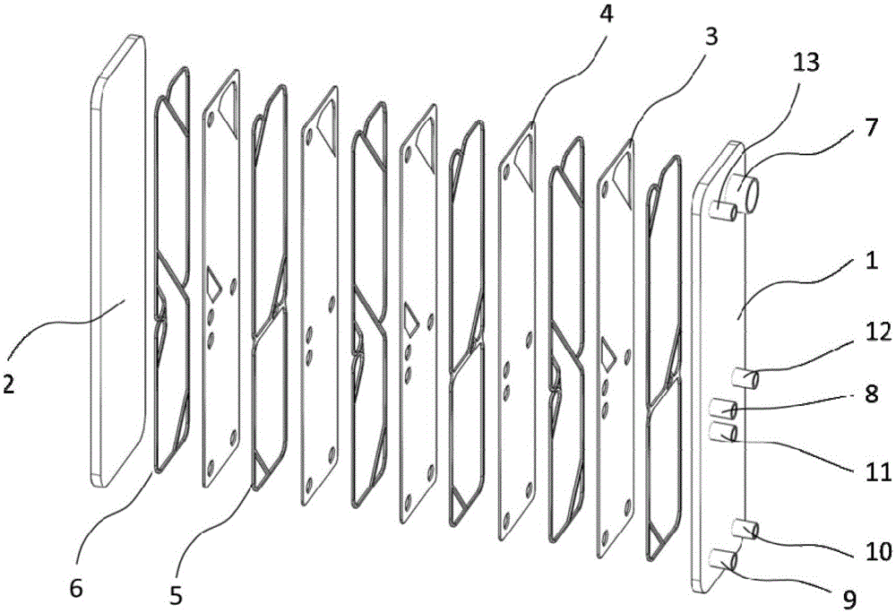
[0024] A plate condenser with liquid separation function, such as Figure 1-7 As shown, it includes a front compression plate 1, a rear compression plate 2 and an intermediate heat exchange module, the front compression plate and the rear compression plate are respectively installed on both sides of the intermediate heat exchange module; the intermediate heat exchange module A cooling water heat exchange flow channel and a steam heat exchange flow channel are provided. The intermediate heat exchange module is composed of several first heat transfer plates 3 and second heat transfer plates 4 stacked sequentially, and a first gasket 5 is arranged between the first heat transfer plates 3 and the second heat transfer plates 4 and the second gasket 6, the first gasket 5 and the second gasket 6 are alternately arranged between the first heat trans...


PUM


Abstract

The invention discloses a plate-type condenser with a liquid separation function. The plate-type condenser with the liquid separation function comprises a front pressing plate, a rear pressing plate and a middle heat exchange module. The front pressing plate and the rear pressing plate are installed on two sides of the middle heat exchange module respectively. The middle heat exchange module is provided with a cooling water runner and a steam runner. The plate-type condenser with the liquid separation function has the beneficial effects that liquid separation is carried out in time, condensate liquid is removed, the thickness of the liquid film of the condensate liquid is effectively reduced, the condensation heat transferring resistance is reduced, and the heat exchange effect of the plate-type condenser is effectively improved; no moving component is included, so that the operation failure rate is small, and reliability is high; the basic structural characteristics of a common plate-type condenser are kept, and the advantages of being good in compactness, small in occupied space, high in heat transferring coefficient and flexible to assemble and use of the common plate-type condenser are inherited; a split-ranging cooling concept is adopted, and the temperature and flow amount of cooling liquid are distributed in a split-ranging mode specific to the change rules of the temperature curve in the process of condensation and heat exchange, so that the temperature matching relationship is more reasonable, the heat transferring temperature difference is effectively reduced, and the exergy loss of the heat exchanger is reduced.

Description

【Technical field】 [0001] The invention relates to the field of condensers, in particular to a plate condenser capable of enhancing phase change heat transfer and being used for steam condensation with liquid separation function. 【Background technique】 [0002] The plate heat exchanger is composed of a series of parallel metal sheets with corrugated surfaces superimposed on each other. The space between the plates forms a channel for heat exchange fluid. The fluid transfers heat through the plates. The effective heat transfer area per unit volume Larger, it has the advantages of compact structure, high heat transfer coefficient, flexible assembly and convenient use. Plate heat exchangers are widely used in industries such as medicine, food and shipbuilding. In the above-mentioned industries, there are many heat exchanges between "liquid-liquid", and the advantages of plate heat exchangers are also obvious. For phase-change heat applications, such as refrigeration and air co...

Claims


Application Information

Patent Timeline
IPC IPC(8): F28B1/02F28B9/08
Inventor 罗向龙许俊俊陈颖杨庆成钟天明
Owner GUANGDONG UNIV OF TECH
Learn More