Detection method of running state of rolling mill position sensor

A detection method and technology for operating status, applied in the field of position sensor working status detection, can solve problems such as frequent failures, sensor wear, abnormal product quality, etc.

Active Publication Date: 2017-09-01
SHANXI TAIGANG STAINLESS STEEL CO LTD
View PDF6 Cites 0 Cited by
  • Summary
  • Abstract
  • Description
  • Claims
  • Application Information

AI Technical Summary

Problems solved by technology

[0002] Position sensors are widely used in rolling mills and steel rolling production lines to achieve position closed-loop control. However, the harsh conditions of high temperature, water vapor, and dust in the working environment, the assembly and wiring of the oil cylinder, the aging of itself leads to frequent failures, and the magnetic ring inside the oil cylinder The wear and tear of the magnetic ring and the sensor caused by the shedding and the assembly part in place will cause inaccurate detection, abnormal product quality, abnormal and out-of-control equipment actions, major equipment accidents, production line shutdown, and economic losses

Method used


Image

  • Detection method of running state of rolling mill position sensor
  • Detection method of running state of rolling mill position sensor
  • Detection method of running state of rolling mill position sensor

Examples


Embodiment Construction

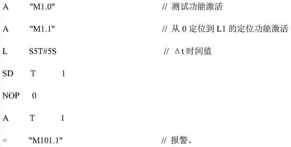
[0014] (1) Detection lag diagnosis: that is, the PLC presets the time Δt for the equipment to run to the given value and the time to reach the given value. The time of the given value is greater than the Δt time, and the PLC will give an alarm;

[0015] Δt=t 2 -t 1 S t 2 -S t 1 2 -S t 1 ) for failure

[0016] S t 2 -S t 1 >100% (S t 2 -S t 1 ) for failure

[0017] t 1 given position start time

[0018] t 2 Time to reach a given location

[0019] S t 1 given position initial value

[0020] S t 2 final value at given position

[0021] S t 2 at t 2 time device position value
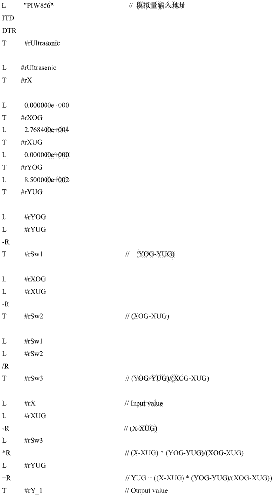
[0022] program:

[0023]

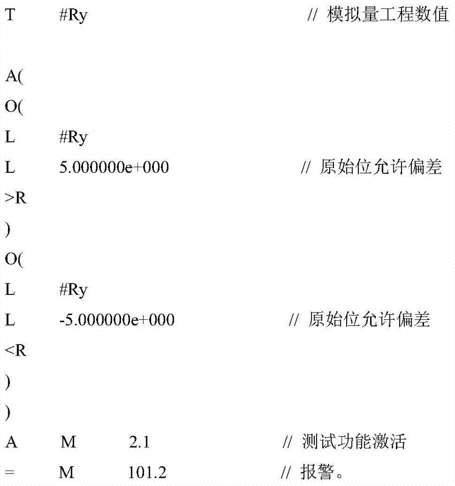
[0024] (2) Deviation from the initial value alarm: that is, the PLC sets the initial position value of the position sensor. When the displacement of the position sensor returns to the initial position and deviates from the initial position value, the PLC alarms;

[0025] program:

[0026]

[0027]

[0028] (3) The rate of change of the signal ...


PUM


Abstract

A method for detecting the running state of a rolling mill position sensor, which includes the following contents: (1) detection lag diagnosis; (2) alarm for deviation from the initial value; (3) change rate of the signal amplitude of the position sensor to time; speed; (5) exceeding the safe relative end position; (6) running in the wrong direction. The present invention comprehensively judges and records the speed, speed change rate, amplitude, and stroke of the sensor through the action state of the field equipment, and realizes comprehensive judgment on the operating state of the position sensor and timely forecast in advance, so as to solve the problem early.

Description

technical field [0001] The invention belongs to the field of position sensor working state detection, and is mainly used for detecting the position sensors of rolling mill side guides and pinch rolls. Background technique [0002] Position sensors are widely used in rolling mills and steel rolling production lines to achieve position closed-loop control. However, the harsh conditions of high temperature, water vapor, and dust in the working environment, the assembly and wiring of the oil cylinder, the aging of itself leads to frequent failures, and the magnetic ring inside the oil cylinder The wear and tear of magnetic rings and sensors caused by falling off and assembly parts in place will cause inaccurate detection, abnormal product quality, abnormal and out-of-control equipment actions, major equipment accidents, production line downtime, and economic losses. [0003] Therefore, it is necessary to conduct real-time self-inspection of the sensor's healthy working status, t...

Claims


Application Information

Patent Timeline
Patent Type & Authority Patents(China)
IPC IPC(8): G01B7/02G05B19/05
Inventor 白文彦李秀平赵伟王永宾
Owner SHANXI TAIGANG STAINLESS STEEL CO LTD
Why Eureka
Try Eureka