An experimental device and method for mine ventilation network system

A mine ventilation network and experiment method technology, applied in the field of mine ventilation network system experiment device, can solve the problems of insufficient function, complex mine ventilation network experiment system manufacturing, high cost, and achieve relatively high cost performance, stable and reliable test system, and easy transformation. Effect

Active Publication Date: 2017-09-22
CHINA UNIV OF MINING & TECH
View PDF6 Cites 0 Cited by
  • Summary
  • Abstract
  • Description
  • Claims
  • Application Information

AI Technical Summary

Problems solved by technology

[0003] Technical problem: the purpose of the present invention is to overcome the deficiencies of the prior art, to provide a simplified mine ventilation network system experimental device, to solve the lack of function of the existing ventilation duct experimental device and the manufacturing difficulties of the complex mine ventilation network experimental system , the problem of high cost

Method used


Image

  • An experimental device and method for mine ventilation network system
  • An experimental device and method for mine ventilation network system
  • An experimental device and method for mine ventilation network system

Examples


Embodiment 1

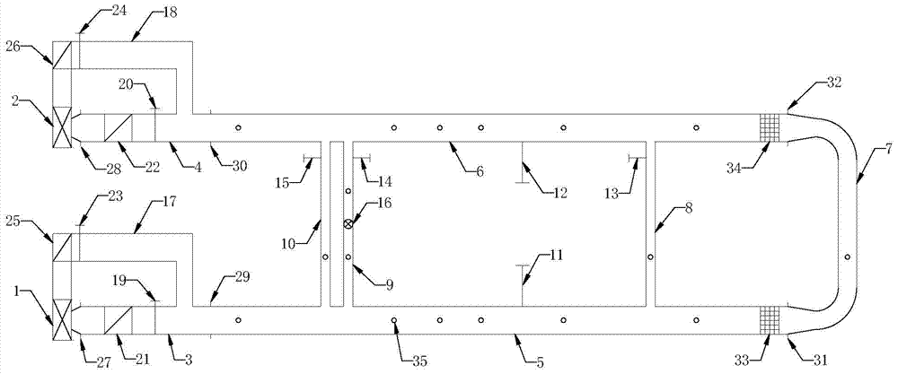
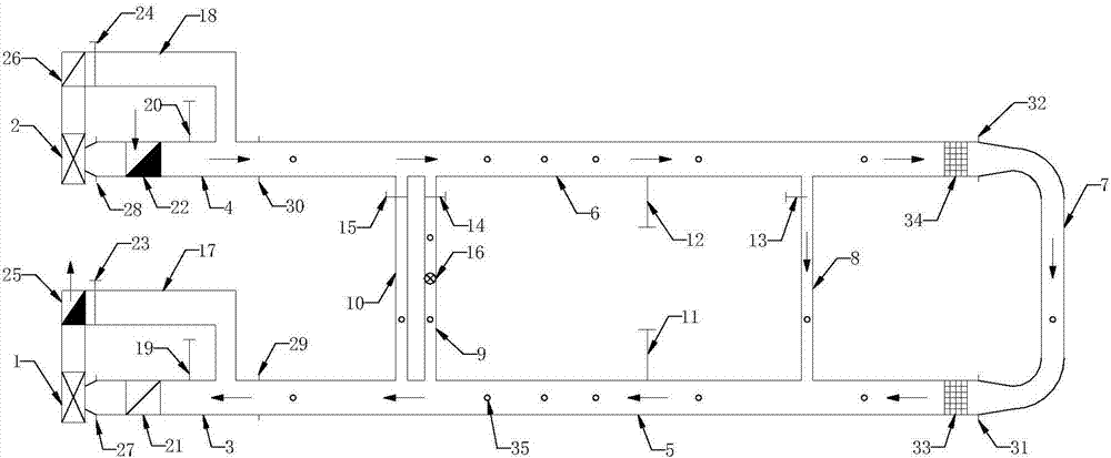
[0041] Embodiment 1, as figure 1 , 2 , 3, 4, 7, and 8, the mine ventilation network system experimental device of the present invention mainly consists of two main straight air ducts, a centrifugal fan, an air tunnel, a connecting air duct, a vertical gate and a rectifying grid. The two main straight air passages mentioned above are set on the same horizontal plane, equal in length and parallel, and the cross-sections of the two main straight air passages are semicircular arched or rectangular, or one is rectangular and the other is semicircular arched, such as Figure 9 and Figure 10 shown. One end of the main straight air duct is respectively provided with a rectifying grid, and the end faces of the two main straight air ducts respectively provided with one end of the rectifying grid are provided with a U-shaped connecting air duct connecting the two main straight air ducts together through a flange , There is a test hole on the U-shaped connecting air duct; the distance...

Embodiment 2

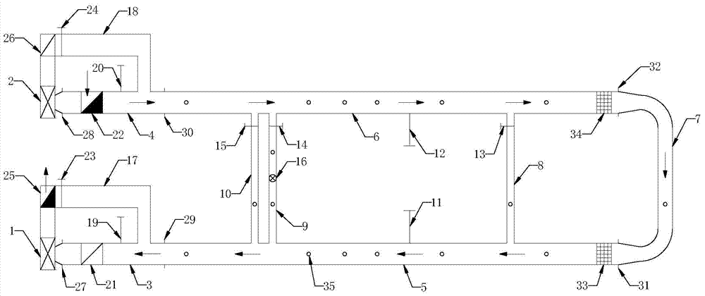
[0045] Embodiment 2, as Figure 5 and Figure 6 As shown, it is basically the same as Embodiment 1, and the same part is omitted. The experimental device of the mine ventilation network system is mainly composed of two main straight air ducts, a centrifugal fan, an air tunnel, a connecting air duct, a vertical gate and a rectifying grid. The two main straight air ducts are located on the same horizontal plane. , equal in length and parallel, the cross-sections of the two main straight ducts are semi-circular arched or rectangular, or one is rectangular and the other is semi-circular arched, such as Figure 9 Figure 10 shown. The other end of the main straight air duct is respectively connected to a frequency conversion centrifugal fan through the air duct. The air duct on the inlet side of the frequency conversion centrifugal fan is provided with a flat gate at the entrance of the duct, a louver valve and a bypass anti-air duct in turn. The outlet of the anti-air duct is ...


PUM


Abstract

The invention discloses a mine ventilation network system experiment device and method, which are suitable for mine ventilation experiments. It consists of two main straight air ducts of equal length and parallel on the same horizontal plane, one end of which is connected to the U-shaped connecting air duct with a flange through a rectifying grille, and the other end is respectively connected to a frequency conversion centrifugal fan through a wind tunnel. The air duct on one side of the centrifugal fan is provided with an inlet flat gate, a louver valve and a bypass anti-air duct in sequence, and a vertical gate and a diffuser outlet flat gate connected with the centrifugal fan are arranged at the exit of the anti-air duct; There are connecting air ducts and circulating connecting air ducts connected in parallel between the main straight air ducts, and a vertical gate is installed in these air ducts, and a variable frequency axial flow circulating fan is installed in the middle of the circulating connecting air ducts. The invention can realize experiments of various ventilation networks and various ventilation modes, has simple structure, convenient operation, strong adjustability, multiple experimental functions and high cost performance, and can provide relatively perfect support for mine ventilation experiment teaching.

Description

technical field [0001] The invention relates to a mine ventilation experiment device and method, in particular to a mine ventilation network system experiment device and method suitable for mine ventilation experiments. Background technique [0002] Mine ventilation system is a complex system composed of mine ventilation network, ventilator and air flow control facilities, among which mine ventilation network is a complex roadway network system connected by open roadway, mining area roadway and mining roadway. Due to its complexity, the current experimental model of the mine ventilation network system is still a demonstrative fixed model. Its manufacturing process is complex, bulky, high in cost, and the functions of ventilation network transformation, adjustment and testing are weak. However, the existing experimental model of tunnel network ventilation on double roads mainly adopts the method of similar simulation experiments to study the influence of different tunnel layo...

Claims


Application Information

Patent Timeline
Patent Type & Authority Patents(China)
IPC IPC(8): G01M9/00
Inventor 陈开岩裴晓东张人伟
Owner CHINA UNIV OF MINING & TECH
Why Eureka
Try Eureka