
electronic signature device

An electronic signature device and electrical connection technology, applied in the direction of digital data authentication, etc., can solve the problems of degaussing, thick carrying of electronic signature equipment, inconvenient magnetic strip bank cards, etc., and achieve the effect of easy portability

Active Publication Date: 2018-04-20
SHENZHEN EXCELSECU DATA TECH
View PDF5 Cites 0 Cited by
  • Summary
  • Abstract
  • Description
  • Claims
  • Application Information

AI Technical Summary

Problems solved by technology

[0003] The purpose of the present invention is to provide an electronic signature device, which aims to solve the technical problems that the existing electronic signature device is relatively thick and inconvenient to carry, and it is easy to demagnetize the magnetic stripe bank card after it is put into the wallet

Method used


Image

  • electronic signature device
  • electronic signature device
  • electronic signature device

Examples


Embodiment Construction

[0024] In order to make the object, technical solution and advantages of the present invention clearer, the present invention will be further described in detail below in conjunction with the accompanying drawings and embodiments. It should be understood that the specific embodiments described here are only used to explain the present invention, not to limit the present invention.

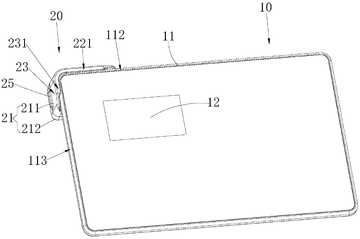
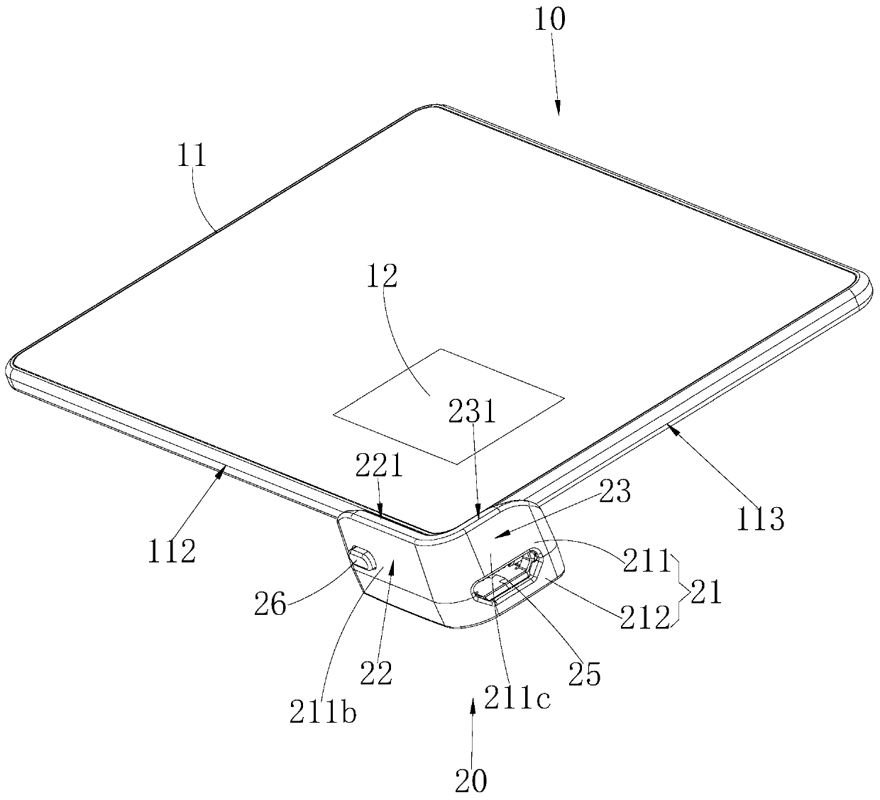
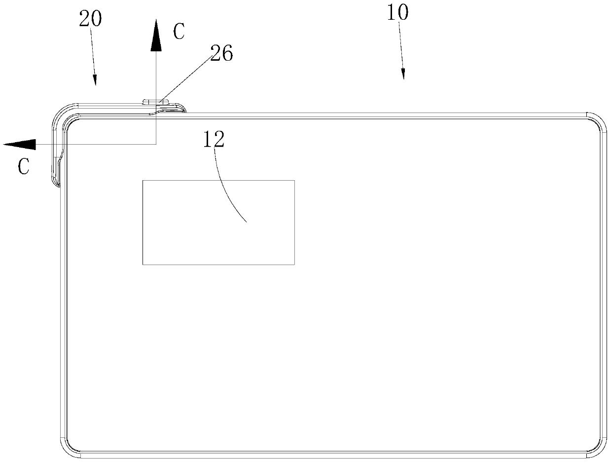
[0025] see Figure 1 to Figure 3 , Figure 7 The electronic signature device provided by the embodiment of the present invention includes a main body 10 and a connector 20 detachably connected to the main body 10; the main body 10 includes a card-shaped first housing 11 with a mounting wall 111, installed on the first The first circuit board (not shown) in the casing 11 and the first interface 13 which is arranged on the first casing 11 and is electrically connected with the first circuit board; please also refer to Figure 6 , the connector 20 includes a second housing 21, a second interface 24 ...


PUM


Abstract

An electronic signature apparatus comprises a card-shaped housing (11), a main body (10) formed by assembling a first circuit board and a first interface (13), a second housing (21), and a connector (20) formed by assembling a second interface (24) and a third interface (25). When the first interface (13) and the second interface (24) are connected via an insertion connection, the connector (20) is connected and fixed to the main body (10). The third interface is adapted, via the first interface (13) and the second interface (24), to the first circuit board to establish a communication connection therewith, and a data line inserted into and disposed on the third interface (25) enables a connection with a terminal apparatus to realize data exchange and charging. The electronic signature apparatus has a thickness equal to that of a bank card and thus can be put in a purse and carried conveniently, thereby realizing mobile payments anytime and anywhere. Moreover, a magnetic attraction structure is adopted to prevent the electronic signature apparatus from being demagnetized by a bank card when placed in a purse, and such a feature has not been disclosed in the prior art.

Description

technical field [0001] The invention belongs to the technical field of electronic signature, and in particular relates to an electronic signature device. Background technique [0002] As mobile payment becomes more and more popular, there are more and more applications of electronic signature devices. The electronic signature device in the prior art usually has a USB interface or a Micro USB interface, and then connects with a terminal device (such as a PC) through a data cable to realize data exchange and charging. This structure makes the electronic signature device relatively thick and difficult to load Wallet, inconvenient to carry. In addition, the electronic signature device in the prior art is usually connected to the data line with a magnetic adsorption structure. If the electronic signature device is magnetically loaded into the wallet and contacts the magnetic stripe bank card, the magnetic stripe bank card will be degaussed and lose its function. Contents of th...

Claims


Application Information

Patent Timeline
Patent Type & Authority Patents(China)
IPC IPC(8): G06F21/34
CPCG06F21/34
Inventor 陈柳章
Owner SHENZHEN EXCELSECU DATA TECH
Learn More