Liquid crystal display panel

A technology for liquid crystal display panels and array substrates, applied in static indicators, nonlinear optics, instruments, etc., can solve the problems of low ESD resistance of test terminals, and achieve the effect of improving efficiency

Active Publication Date: 2015-11-18
WUHAN CHINA STAR OPTOELECTRONICS TECH CO LTD
View PDF5 Cites 35 Cited by
  • Summary
  • Abstract
  • Description
  • Claims
  • Application Information

AI Technical Summary

Problems solved by technology

[0009] The purpose of the present invention is to provide a liquid crystal display panel to solve the te

Method used


Image

  • Liquid crystal display panel
  • Liquid crystal display panel
  • Liquid crystal display panel

Examples


Embodiment Construction

[0057] The following descriptions of the various embodiments refer to the accompanying drawings to illustrate specific embodiments in which the present invention can be practiced. The directional terms mentioned in the present invention, such as "up", "down", "front", "back", "left", "right", "inside", "outside", "side", etc., are for reference only The orientation of the attached schema. Therefore, the directional terms used are used to illustrate and understand the present invention, but not to limit the present invention. In the figures, structurally similar units are denoted by the same reference numerals.

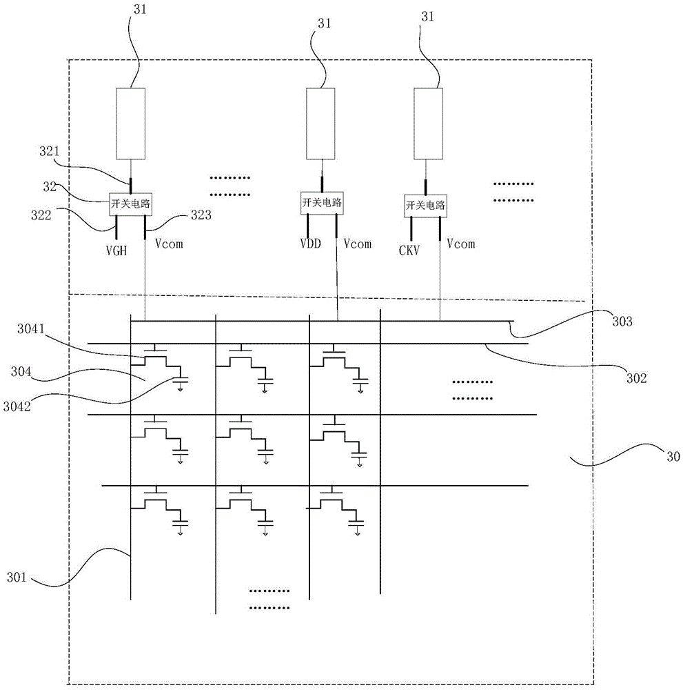
[0058] This embodiment provides a liquid crystal display panel, such as figure 2 shown, including:

[0059] The array substrate 30 includes: a plurality of data lines 301, a plurality of scanning lines 302, a common electrode line 303 and a plurality of pixel units 304; in this embodiment, the array substrate 30 may be a GOA substrate;

[0060] The data line 301 i...


PUM


Abstract

The invention provides a liquid crystal display panel. According to the liquid crystal display panel, each test terminal at the periphery of an array substrate is provided with a switch circuit, when static electricity on the test terminals needs to be released through the switch circuits, all the test terminals are connected with a common electrode wire, and the static electricity is released through the common electrode wire, such that the anti-ESD capability of the test terminals is enhanced, and the service life of the liquid crystal display panel is prolonged.

Description

【Technical field】 [0001] The invention relates to the technical field of liquid crystal displays, in particular to a liquid crystal display panel. 【Background technique】 [0002] At present, most of the small sizes adopt the GOA design (ColorfilterOnArray, the color filter layer is formed directly on the array substrate), and peripheral test pads (terminals) are designed on the left and right ends of the OLB (Outleadbonding, lead welding) terminal area. Peripheral test terminals mainly include test terminals that provide control signals to the Gate (gate), such as those that provide signals such as VGH (turn-on voltage of thin-film transistors) / VGL (turn-off voltage of thin-film transistors) / VDD (internal voltage of the device) / CKV Test terminals; test pads that provide Vcom (in-plane common voltage) to the panel; and test pads related to source driver chips. [0003] These test pads are mainly used for CellTest (liquid crystal display panel testing) and post-analysis testi...

Claims


Application Information

Patent Timeline
IPC IPC(8): G09G3/00G02F1/1362
Inventor 文松贤
Owner WUHAN CHINA STAR OPTOELECTRONICS TECH CO LTD
Why Eureka
Try Eureka