
Double-track frame demagnetizer

A demagnetizer and double-track technology, applied in the direction of magnetic objects, electrical components, circuits, etc., can solve problems such as difficult to meet the use requirements and single function of the demagnetizer, and achieve the effects of convenient control, enhanced demagnetization, and simple overall configuration

Inactive Publication Date: 2015-11-18
WUHU HAILIAN MACHINERY INSTALLATION
View PDF8 Cites 3 Cited by
  • Summary
  • Abstract
  • Description
  • Claims
  • Application Information

AI Technical Summary

Problems solved by technology

The function of the demagnetizer with this structure is relatively single, and it is difficult to meet the requirements of various occasions.

Method used


Image

  • Double-track frame demagnetizer

Examples


Embodiment Construction

[0013] The present invention will be further described below with reference to the accompanying drawings and in conjunction with the embodiments.

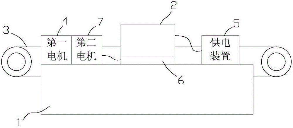
[0014] refer to figure 1 , The frame-type demagnetizer of the present invention is mainly composed of a frame 1, a frame-type demagnetization coil 2, a conveyor belt 3, a first motor 4, a power supply device 5, a support member 6 and a second motor 7. The first motor 4 is fixed on the frame 1 and is used to drive the conveyor belt 3 to move. When working, the bearing parts that need to be demagnetized are placed on the conveyor belt 3 and follow the movement of the conveyor belt 3 . The frame-type demagnetization coil 2 is powered by a power supply device 5. The power supply device 5 includes a transformer. By supplying alternating current to the frame-type demagnetization coil 2, the coil 2 generates a magnetic field. When the bearing passes through the magnetic field, the residual magnetism inside it will be eliminated. . In o...


PUM


Abstract

The invention discloses a double-track frame demagnetizer, which comprises a rack, a frame demagnetizing coil, a conveyor belt, a first motor and a power supply device, wherein the first motor drives the conveyor belt to move; the power supply device supplies electricity to the frame demagnetizing coil to control the frame demagnetizing coil to work; the first motor is fixed on the rack; a support member capable of carrying out linear movement along the rack and a second motor for driving the support member to move are arranged on the rack; the frame demagnetizing coil is fixed on the support member; and the conveyer belt passes through the frame demagnetizing coil and can move in the direction parallel to the movement direction of the support member. According to the double-track frame demagnetizer, the conveyor belt can displace and the demagnetizing coil can also move; and when the double-track frame demagnetizer is used, a bearing part with a fixed position can be demagnetized only by controlling the demagnetizing coil to move. The position can be kept invariable when the bearing part is demagnetized, so that the control is relatively convenient when station transferring on the bearing part is carried out through a mechanical arm; the overall configuration is relatively simple; and when the double-track frame demagnetizer works, the effect of strengthening demagnetizing can also be put into a play through coordinating movement of the conveyer belt and the demagnetizing coil.

Description

technical field [0001] The invention relates to bearing cleaning equipment, in particular to a double-track frame-type demagnetizer. Background technique [0002] Bearing production usually adopts the method of electromagnetic centerless fixture processing, and the processed bearing is adsorbed on the fixture and fixed before processing. After processing, the bearing will have residual magnetism, and the existence of residual magnetism will greatly affect the quality and life of the bearing. Therefore, a demagnetizer will be configured to demagnetize the bearing during bearing cleaning. In traditional demagnetizers, the finished bearing is placed on the conveyor belt, and then the conveyor belt drives the bearing through the demagnetization coil to achieve demagnetization. The function of the demagnetizer with this structure is relatively single, and it is difficult to meet the use requirements of various occasions. Contents of the invention [0003] In order to solve t...

Claims


Application Information

Patent Timeline
Patent Type & Authority Applications(China)
IPC IPC(8): H01F13/00
Inventor 张和平汪雷李其炳
Owner WUHU HAILIAN MACHINERY INSTALLATION
Learn More