Phase shifter with built-in transmission rod

A technology of transmission rod and phase shifter, which is applied to waveguide-type devices, electrical components, circuits, etc., can solve the problems of increasing assembly difficulty, increasing the difference in the displayed value of the down-tilt angle scale, and increasing the cost, so as to optimize the down-tilt angle. Accuracy, the effect of reducing potential intermodulation points, and reducing the number of parts

Active Publication Date: 2015-11-18
WUHAN HONGXIN TELECOMM TECH CO LTD
View PDF7 Cites 12 Cited by
  • Summary
  • Abstract
  • Description
  • Claims
  • Application Information

AI Technical Summary

Problems solved by technology

[0004] Existing base station antenna design manufacturers: In the design of the dielectric sliding phase shifter, the transmission rod is placed outside the phase shifter cavity, which requires the design of the guide parts of the transmission rod and the connection between the dielectric sheet and the transmission rod components, which increases the difficulty of assembly; due to the cumulative tolerance of the assembly of the connecting parts, the difference between the displayed value of the downtilt angle scale and the actual downtilt angle is increased; because the transmission rod and the dielectric sheet are designed to be connected on one side, the dielectric sheet is in one direction. When moving in one direction, it is affected by tension, and when moving in the other direction, it is affected by thrust. When the dielectric sheet is subjected to thrust, the edge of the dielectric sheet will rub against the PCB, which will deteriorate the surface quality of the PCB and affect the third-order intermodulation performance of the phase shifter.
When welding the PCB and the coaxial cable, in order to ensure the continuity of the transmission line, the outer conductor of the coaxial cable and the welding block are welded first, and then the welding block is fastened to the cavity of the phase shifter by screws, and the welding block and the welding block are additionally added. Fasteners increase the difficulty of assembly while increasing the cost, and introduce new hidden dangers of third-order intermodulation

Method used


Image

  • Phase shifter with built-in transmission rod
  • Phase shifter with built-in transmission rod
  • Phase shifter with built-in transmission rod

Examples


specific Embodiment approach

[0058] A specific implementation of a phase shifter with a built-in transmission rod in one embodiment is as follows:

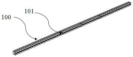
[0059] like Figure 9 As shown, the phase shifter includes four dielectric sheets 300, two PCB400, and one built-in transmission rod 100;

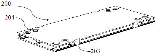
[0060] The built-in transmission rod 100 is located in the middle of the cavity 201 of the phase shifter, the four dielectric sheets 300 and the two PCB400 are respectively located on both sides of the built-in transmission rod 100, and each of the PCB400 is sandwiched between two between 300 dielectric sheets. Specifically, push two PCB400, four dielectric sheets 300, and a built-in transmission rod 100 along the first position-limiting protrusion structure 205 in the cavity 200 of the phase shifter, and push the rectangular groove 207 into it to solder the PCB400. The disk 403 is directed against the welding hole 204 on the wall of the phase shifter cavity 200 .

[0061] One side of each of the dielectric sheets 300 ...


PUM


Abstract

The invention discloses a phase shifter with a built-in transmission rod. A PCB is clamped between two dielectric pieces, three clamping buckles of each dielectric piece are inserted into corresponding circular holes of the built-in transmission rod through micro deformation, two sides of the PCB are clamped in a rectangular groove of an empty cavity and a second rectangular groove of the built-in transmission rod, a cavity body of the phase shifter is manufactured by adopting an aluminum alloy extruded section structure, and first limiting projection parts in the cavity body of the phase shifter are used for limiting and guiding the built-in transmission rod, thereby optimizing precision of a downward inclination angle, reducing number of components, saving assembling time and reducing intermodulation hidden danger points. An insulating layer of a coaxial cable passes through a circular hole at the bottom part of a semicircular trench, an inner conductor is lapped on a PCB welding pad for welding, a welding process circular hole is formed in a cavity body wall of the phase shifter just above the PCB welding pad for welding the welding pad, and an outer conductor of the coaxial cable is directly welded on a semicircular trench in the external part of a section, thereby reducing number of components, saving assembling time, reducing the risk that welding points are damaged, and reducing intermodulation hidden danger points.

Description

technical field [0001] The invention relates to the technical field of base station antennas for mobile communications, in particular to the field of phase shifters for base station antennas, and in particular to a phase shifter with a built-in transmission rod. Background technique [0002] In a wireless communication system, the base station antenna is the interface between the transceiver and the external propagation medium. With the development of wireless communication, the complex and changeable network environment and the shortage of site and steel structure communication tower platform resources, the requirements for base station antennas are usually higher. The electronically adjustable antenna can realize the continuous adjustment of the downtilt angle of the vertical beam, and the network coverage is more flexible. The beam inclination angle of the electronically adjustable antenna can be changed through remote control as needed, and the coverage effect is better...

Claims


Application Information

Patent Timeline
Patent Type & Authority Applications(China)
IPC IPC(8): H01P1/18
Inventor 吴卫华丁勇张申科程季
Owner WUHAN HONGXIN TELECOMM TECH CO LTD
Why Eureka
Try Eureka